Page 5
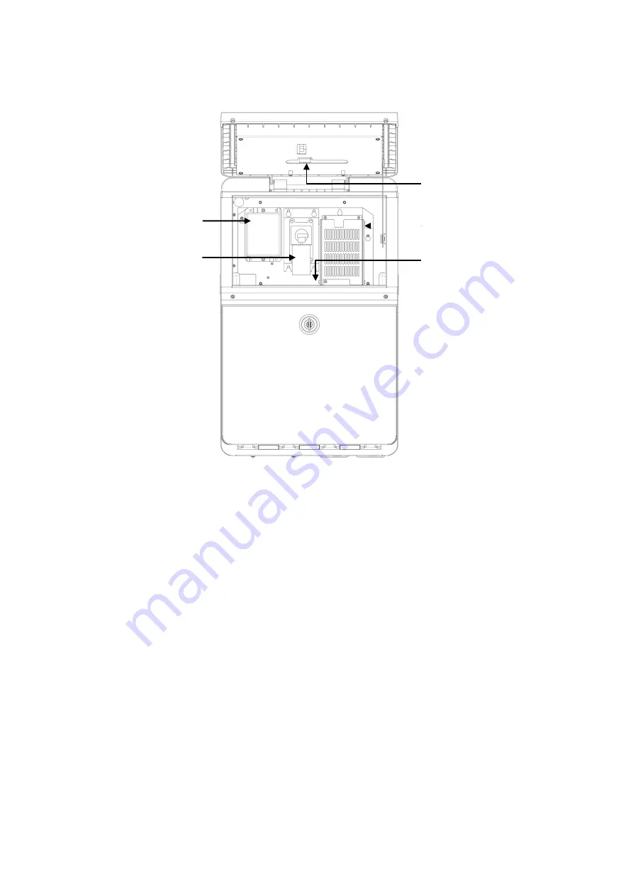
2.4 Electrical System
5
1
4
2
3
Instructions for direction:
1. Extra High Tension (EHT/HV)
2. Positive Air Pump (Some models do not include
)
3. Mainboard (Not visible from this view)
4. Power Supply Unit
5. Display driver board
Page 1: ...DuraCode Series DURACODE 200 SERIES TOUCHSCREEN Continuous Inkjet Printer OPERATION MANUAL www inkjetinc com 1 800 280 3245...
Page 2: ...erence at his own expense 2006 42 EC Machinery Directive 2014 35 EU Low Voltage Directive 2014 30 EU Electromagnetic Compatibility Directive EN ISO 12100 2010 Safety of machinery General principles fo...
Page 3: ...ystem 5 3 Operating Software 6 3 1 Home Page 6 3 2 Run Info 7 3 3 Print Mode 8 3 4 Print Management 10 3 4 1 Select Printing Information 10 3 4 2 Print Editing 11 3 4 3 Print Parameters 12 3 4 4 Text...
Page 4: ...Stop and clean the ink jet printer 36 5 3 1 Stop and clean 36 5 3 2 Shutdown and cleaning power off during use 36 5 3 3 Shutdown and cleaning long term stop 36 5 4 Failure and warning icons 37 5 4 1...
Page 5: ...source fire source and static electricity Smoking near the ink jet printer is prohibited The covers of the containers for the printing ink solvent and cleaning agent used for the ink jet printer must...
Page 6: ...ntained at the vertical state the printing ink and solvent shall be completely discharged before handling 1 5 Responsibilities During use and maintenance of the equipment the company shall not be resp...
Page 7: ...ts 2 1 Overview Right View Front View Left View Instructions for direction 1 Main power switch 2 Upper overview Electronics Compartment and Control Panel 3 Lower overview Ink compartment 4 Connector P...
Page 8: ...Charge Electrode Nagetive Deflection Plate Phase Detector Positive Deflection Plate Gutter Sensing Tube 2 3 Ink Module Condenser Cover Exhaust Air Switch Manifold Socket V6 Filter ExhaustVentPlug Dra...
Page 9: ...Electrical System 5 1 4 2 3 Instructions for direction 1 Extra High Tension EHT HV 2 Positive Air Pump Some models do not include 3 Mainboard Not visible from this view 4 Power Supply Unit 5 Display d...
Page 10: ...and the main window is shown in the following figure 1 2 3 4 5 6 7 Instructions for direction 1 Device Status Bar 2 Error and Warning Information Bar 3 Current Message Details Bar 4 Back Zoom out and...
Page 11: ...and the number of phase 6 Measuring Cup The level of fluid in the measuring tank High indicates filled Low indicates empty 7 Chamber Liquid level state of the viscosity detection chamber High to show...
Page 12: ...onal 2 Photocell 1 o Level Printing is triggered when the photocell 1 obtains the high or low level signal Set according to sensor used o Blocking time This is a time in milli seconds to inhibit the t...
Page 13: ...alternate prints on forwards traverse o Opposite Opposite delay Sets the delay on first print of the return traverse Print Count Use to set opposite print times Print Interval Set the interval between...
Page 14: ...a Touch This Area 3 Select from here 4 Then Click To Print 3 4 Message Management 3 4 1 Select Printing Message 1 Follow the steps as follow 2 Enter Manage Job interface 3 Select the job from the list...
Page 15: ...low 2 Enter Edit interface 1 3 4 2 5 Instructions 1 The message contents display in this area 2 Use to move the contents position 3 All the contents will list here 4 All kinds of contents here can be...
Page 16: ...be Delay Range 3 10000 Sets the printing delay time This sets the time from the print trigger to the start of printing position 2 Width This setting adjusts the width of print The smaller the value is...
Page 17: ...lected 3 Tower print 0 and 90 can be selected the single line text can be printed in the tower shaped font if it set to 90 4 ID Field name of the single line text for fast selection 5 X Y Position of...
Page 18: ...lt Text parameters ID Field name of the Mult Text for fast selection Width Height Size of the layout Width maximum 4000 dots X Y Position of the Mult Text in the message Fonts parameters Fonts 5 6 5 7...
Page 19: ...5 6 5 7 4 7 9 11 16 24 32 dot matrix fonts can be selected Deviation Days in advance to print 4 Tower print On selection the single line text can be printed in the tower shaped font Raster Bowdleriza...
Page 20: ...setting interface is as follows Content agreement Jet printing format Instructions for direction 1 Start value End Value Starting value and end value of the counter The maximum value which can be inp...
Page 21: ...Page 17 Repeat Count 1 at default printing times of each current value For example if set as 2 each counter value will be printed for 2 times...
Page 22: ...front of the 6 digit counting value Current Value Current Value of the counter 5 System Base format of the counter Jet printing format Refer to section 3 4 4 3 4 9 Picture At the print editing interfa...
Page 23: ...Bolding of 1D Barcode 0 9 bolding times can be selected 6 X Y Coordinates of the position of Barcode 7 Width Height Size of barcode 1D Barcode is automatically generated 8 Reverse and Inverted Orienta...
Page 24: ...d Ext Data The interface is as follows 1 2 Instructions for direction 1 Code The identification code of external data communication is correspondingto the user area in the calculation software Length...
Page 25: ...k the corresponding transmission icon to transmit print layout between the system and USB disk The file will also include the print parameters 3 4 13 Photo management Touch the message area at the hom...
Page 26: ...r the system setting main interface as shown in the following figure 4 1 Authorization At the Settings interface click the Authorization setting icon The interface can be set with passwords of two lev...
Page 27: ...lly Gutter Mode Sets the recovery mode of ink through the gutter Modulation Set Sets the nozzle modulation value 2 Speed Ratio This setting affects ratio of a Width b Delay c Internal intervald Extern...
Page 28: ...4 Cleaning Click the icon of Cleaning in the Settings to enter the Cleaning interface as shown in the figure Instructions for function option 1 Wash Nozzle Nozzle used for automatic washing of blockag...
Page 29: ...e pressure 5 Clean Ink System Used for cleaning of the whole ink system 6 Exhaust Air From Ink System Used to empty air in the ink way for example use during the first use 7 Fill Mixer Used to Fill th...
Page 30: ...26 4 7 EHT Setting Used to assign EHT values to different print height The values have been set before the machine leaving the factory and usually there is no need to set it again during use...
Page 31: ...nction option 1 IP Addr Used to set the IP address 2 Subnet Mask Used to set the Subnet Mask 3 Default Gateway Used to set the Default Gateway 4 DNS Used to set the DNS 5 Local Port Used to set Local...
Page 32: ...28 4 9 Character Format Different styles of characters 0 1 and 5 can be selected here the printer needs to be reboot when the styles changed...
Page 33: ...the baud rate 2 Tranc Model Used to choose the transfer mode Printed Tranc end 3 External data Printing Non repeating printing Printer only print the latest data once Print the latest data Printer wil...
Page 34: ...tion This can be used for calibration when the touch screen key position is inaccurate Press the cross icon in turn to complete the calibration 4 13 System Time Date Used to calibrate system time of t...
Page 35: ...o define the printed date information including year month day hour and minute For example With reference to above picture to modify what is printed for the current year modify the code of 17 to a req...
Page 36: ...32 4 17 About Click the icon of About in the Settings to enter the interface as shown in the figure Instructions 1 Software version it can be update by USB...
Page 37: ...door 4 Connect the printer to an appropriate power source and power on the printer 5 EntertheSETINGS INKSYSTEMmenu perform FillMixerprogramwaitforabout30 minutes until the screen shows Fill Mixer Tan...
Page 38: ...press the power button at right of the printer and wait for the screen to enter the mainoperation interface 4 Click and select Start Jet to start the printing jet 5 Observe the state indicator lamp a...
Page 39: ...lignment Description after the printer has started the ink jet is sprayed from the nozzle and recycled by the gutter pipe Side view Front view Prompt For ink jet adjustment method see the section of 5...
Page 40: ...ate and stable pressure Correct ink viscosity Correct ink dot modulation value The observation method is as follows 1 Take out the magnifying glass in the standard configuration and place it about 15m...
Page 41: ...tatus bar has shown STOPPED the power supply of the inkjet printer can be turned off 5 3 2 Shutdown and cleaning power off during use If abnormal shutdown of the equipment is caused due to power off i...
Page 42: ...ew ink Filter blocked Replace the filter For details please consult the service engineer Gutter Fault The nozzle is blocked or miss aligned ink jet Ink not entering the gutter Clean the nozzle clean p...
Page 43: ...ink Cartridge Printhead cover open The printhead cover is opened the printer cannot print Fit the printhead cover to enable printing Viscosity failure Ink viscosity failure indicates the ink is out o...
Page 44: ...rinthead and the printing surface The character height is too small or too large Reset the character height The character width is too small or too large Reset the character width Wrong breakpoint sha...
Page 45: ...width or printing delay No print on product Check sensor sensitivity Wrong or unstable Ink jet position Reason Solution Nozzle blockage Clean the nozzle See 5 6 Nozzle cleaning Filter blockage The tr...
Page 46: ...ck either Nozzle Flush or Wash Nozzle The printer will execute the program and automatically complete a Nozzle Flush Internal wash of the nozzle using solvent from solvent cartridge Need to place a co...
Page 47: ...rizontal alignment Slightly loosen the screw A and rotate the screw B slightly then the jet stream can be horizontalmoved Verticalalignment Loosenthe screw C and rotatethescrew D slightly then the jet...
Page 48: ...cleaning Enter Settings Ink System and click System Cleaning complete the system cleaning operation according to screen prompt 5 9 Sensor and Encoder wiring diagram 5 9 1 Sensor diagram 5 9 2 Encoder...
Page 49: ...V AC Frequency 50 Hz to 60 Hz Power Consumption 120 watts maximum Weight Dry weight 27 KG Dimensions Cabinet Width 345 mm Height 570 mm Depth 286 mm Printhead Diameter 41mm Diameter of the nozzle ori...