


06
I
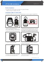
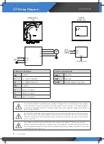
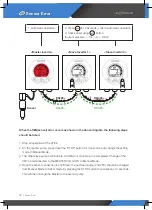
Wiring Diagram
Wiring Diagram
This manual is intended as a guide for proper installation. Injungtech Co., Ltd., cannot assume responsibility
for the compliance or the non-compliance to any code, national, local or otherwise, for the proper installation
of this drive or associated equipment. A hazard of personal injury and/or equipment damage exists if codes are
ignored during installation.
This INJ-4500 contains high voltage capacitors that take time to discharge after removal of the main supply.
Before working on the drive, ensure isolation of the main supply from line inputs. Wait ten (10) minutes for the
capacitors to discharge to safe voltage levels. Failure to observe this precaution could result in severe bodily
injury or loss of life.
Only qualified electrical personnel familiar with the construction and operation of this equipment and the
hazards involved should install, adjust, operate, or service this equipment. Read and understand this manual
and other applicable manuals in their entirety before proceeding. Failure to observe this precaution could result
in severe bodily injury or loss of life.
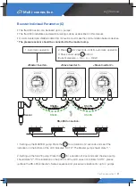
U
V
W
FG
L1/R
L2/T
FG
M
~
FG
FG
R
T
V
W
U
2Ph2C,220V,
50Hz
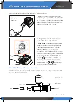
SEN+
SEN-
PRESSURE
SENSOR
4~20mA
SEN+
SEN-
TO.POWER BOARD
FROM.
12PIN
POWER BORAD
LINE
CONTROL
BORAD LINE
Power Connections
FG
EARTH
T
L2/T(INPUT POWER)
R
L1/R(INPUT POWER)
FG
EARTH
U
Motor connection
V
Motor connection
W
Motor connection
Control Connections
SEN +
SEN -
SENSOR-
12PIN
POWER BORAD Connection


