background image

Getting started

12

iPoMan 8000

2. To configure the iPoMan 8000, you can use the console or WAN 

port. Connect the iPoMan 8000 to a console and a WAN to enable its 
configuration through the console or browser menu.

3. After connecting to a console, use a console application such as Tel-

net or HyperTerminal to access the console menu. Select the 

System 

Group

 submenu under the 

iPoMan Configuration

 to set up the IP 

address and the system date/time. This IP address will be used while 
accessing the web interface to configure the iPoMan 8000 parame-
ters.

4. After connecting to WAN, open a browser from a PC in the network 

and use the iPoMan 8000 IP address specified through the console 
menu to open the web interface for system configuration.

The following sections provide instructions about how to make various con-
nections.

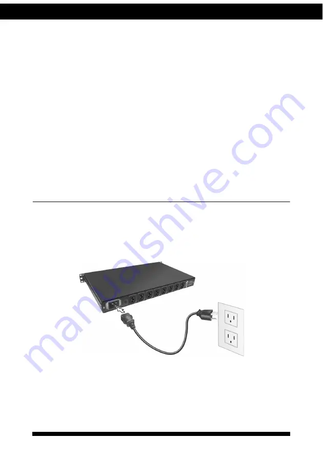
Connecting input power

The iPoMan 8000 has an IEC C20 power inlet for supplying and managing 
power for the output devices. Connect the power cord to the power inlet and 
plug the other end into a power outlet as shown:

Summary of Contents for iPoMan 8000

Page 1: ...iPoMan 8000 User Manual...

Page 2: ......

Page 3: ...ted transcribed stored in a retrieval system or translated into any language in any form or by any means except documen tation kept by the purchaser for backup purposes without the express writ ten pe...

Page 4: ...st be per formed by qualified service personnel Remove rings watches and other jewelry before servicing the unit Before maintenance repair or shipment the unit must be completely switched off and unpl...

Page 5: ...ttons 7 Rear panel 9 Getting started Attaching the feet 10 Attaching the ears 10 Making connections 11 Connecting input power 12 Connecting output devices 13 Connecting digital outputs 13 Connecting E...

Page 6: ...tting the date and time 22 Adding users 23 Changing event alert settings 23 Modifying application settings 24 Setting control options 24 Setting up a schedule 25 Status 25 Configuration 25 Appendix Sp...

Page 7: ...ch can be moni tored and controlled through the console or web interfaces You can also use the front panel to operate the power outlets The iPoMan 8000 is also equipped with a console port for connect...

Page 8: ...t occurrence or planned schedule Comprehensive power management and flexible configuration through web browser NMS Telnet SNMP or HyperTerminal console Configurable user security control User friendly...

Page 9: ...kage has the following items If any of items is missing or damaged contact your nearest service center or vendor 1 iPoMan 8000 2 Ears x2 3 U type handle x2 4 U type handle screws x4 5 Ear screws x6 6...

Page 10: ...wer status indicator A H Displays output current power status and remote control status for each power outlet A through H 2 Input power consump tion indicator Displays percentage of input power consum...

Page 11: ...the iPoMan 8000 S1 off S2 off Normal operation default mode 7 Serial CONSOLE port Enables you to configure the iPoMan 8000 using the serial port You can also connect an optional EMD to this port 8 Et...

Page 12: ...through the power outlet 2 Outlet power indicator Displays the out let power status Grey power off Green power on 3 Remote control indicator Displays the remote control status of each outlet Grey remo...

Page 13: ...1 Press the control button once The remote control indicator starts flashing red 2 Now press control button again within 5 seconds and hold for more than 5 seconds The remote control indicator starts...

Page 14: ...Now press control button again within 5 seconds and hold for more than 5 seconds The outlet power indicator starts flashing green at a faster speed and then inverts its original state For instance if...

Page 15: ...system 3 Power outlet A H Connect a device to each power outlet to sup ply power to it 4 Dry contact port Connect dry contact UPS that can be remotely managed through network card This is cur rently n...

Page 16: ...PoMan 8000 comes with four feet or spacers that are attached to the bottom Use the four screws provided with the feet to attach the feet to the bottom of the iPoMan 8000 as shown Note You do not need...

Page 17: ...lso supports an EMD Environmental Monitored Device or sensors for detecting environmental conditions as well as digital outputs or devices with normally open or nor mally closed conditions Moreover th...

Page 18: ...and the system date time This IP address will be used while accessing the web interface to configure the iPoMan 8000 parame ters 4 After connecting to WAN open a browser from a PC in the network and u...

Page 19: ...rough the LAN and Console ports Connect the power connectors of the devices to each of the power outlets A through H with the power cords supplied with the devices as shown Connecting digital outputs...

Page 20: ...hat is connected to sensors for detect ing temperature humidity water level and so on can be connected to the iPoMan 8000 with the console port The EMD can also be connected to alarms or indicators an...

Page 21: ...rminal or Telnet Connecting to a WAN The iPoMan 8000 has an RJ 45 LAN connection that enables you to monitor and manage the power outlets and digital outputs over the network The iPoMan 8000 has a gra...

Page 22: ...ble Using HyperTerminal HyperTerminal is a console application in Windows that enables you to con figure or control a device through command line parameters You can con figure the iPoMan 8000 paramete...

Page 23: ...Click OK when done 4 The Properties window opens Click Restore Defaults to use the default settings Make sure that the Bits per second field is set to 9600 Click OK when done 5 Press any key The iPoM...

Page 24: ...enu type 1 and press Enter Submenus may have further nested menus which can also be accessed by typing the appropriate number To modify a menu option select the option with its corresponding number an...

Page 25: ...n trol group submenu to enable input phase detection which allows the iPoMan 8000 to turn off outlet power if there is a phase mismatch Outlets Control This enables you to control all power outlets an...

Page 26: ...tem Group under the iPoMan Configuration menu 2 Select the IP Address item and set the IP address This address lets you access the iPoMan 8000 in a TCP IP network LAN WAN Con tact your system administ...

Page 27: ...even your mobile phone This section provides instructions about how to use the web interface to config ure and control the iPoMan 8000 remotely Overview Start a web browser such as Internet Explorer f...

Page 28: ...8000 Click the icon at the top of each page to view the help To go back to a previous menu click the icon at the top of the page Modifying the basic settings The System menu enables you to configure...

Page 29: ...st Changing event alert settings The iPoMan 8000 sends email or SNMP trap alerts to specified users when specific events occur Use the following steps to set up these alerts Click Trap Receivers under...

Page 30: ...mouse cursor over the inlet or any of the outputs and click to configure them as follows Inlet Specify what action is taken by the iPoMan 8000 when the inlet voltage is not within limits You can set w...

Page 31: ...he outlets that you want to control and specify if you want to turn the outlets on or off Status Click Status under Environment to see the status of the EMD connected to the iPoMan 8000 The menu page...

Page 32: ...p for each outlet iPoMan 8000 220V model AC Input IEC C20 inlet 15 Amp 200 250 VAC 50 60Hz AC Output IEC C13 outlet 10 Amp 200 250 VAC 50 60Hz Load 10 Amp for each outlet or 15 Amp total Dimensions an...

Page 33: ...ration Menu and set the Input Phase Detection item to Disabled Description Error code Network link down E01 Parameters checksum error E02 Input voltage over threshold high Volt E03 Input voltage over...

Page 34: ...at interference will not occur in a particular installation If this equipment does cause harmful interference to radio or television reception which can be determined by turning the equipment off and...

Page 35: ...R Class B standard EN 55024 Electromagnetic compatibility Generic immunity stan dard Part 1 Residential and light industry UL The product is qualified per UL Underwriters Laboratory 1950 Third Edi tio...

Reviews: