background image

Manual - vhp300cm

- 34 

06/20/00

LUBRICATION

Both compressor lubrication and cooling are
accomplished by the compressor lubricating oil.
The oil is forced from the oil storage reservoir,
under system pressure, through an oil cooler and
an oil filter directly to the compressor.  When the
compressor is operating at low capacity, some of
the oil may bypass the cooler through a
thermostatically controlled bypass valve.  This
valve bypasses varying amounts of oil,
depending upon the temperature, until the oil
being circulated reaches a temperature of 185

°

F

(85

°

C) thus maintaining a higher average oil

temperature thereby reducing the possibility of
water vapor condensation in the oil.

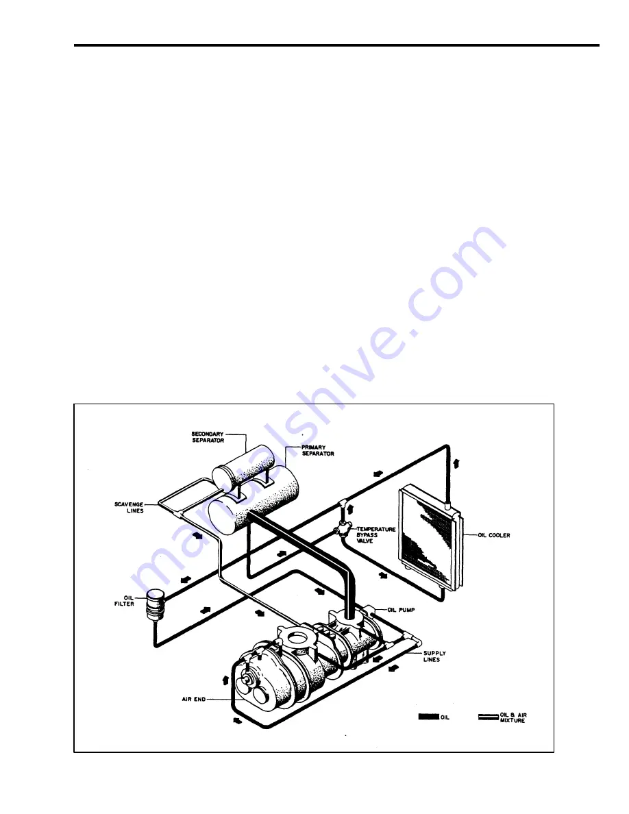
Typical Lubricating and Cooling Oil System

Relatively cool lubricating oil is admitted under
pressure to the compressor bearings and is also
injected in metered amounts, directly to the rotor
chamber.  All of the oil thus introduced mixes
with, and passes on with the air being
compressed, thus removing the heat of
compression to a large degree.  On its way to the
final discharge connection, the air passes through
a receiver/separator.  A scavenger line returns
any remaining separated oil back to the inlet of
the compressor.

Fill the oil storage reservoir in the
receiver/separator with new oil before operating
the unit.  Recharge the compressor by first
removing the air filter and pouring about two
gallons (7.57 liters) of oil into the compressor
inlet.

NOTE

Recharging of the compressor with oil is
absolutely necessary on units that have been
placed in extended storage (6 months or more).

Summary of Contents for VHP300CM

Page 1: ...212257 CD ROM P N 43212265 Doosan purchased Bobcat Company from Ingersoll Rand Company in 2007 Any reference to Ingersoll Rand Company or use of trademarks service marks logos or other proprietary ide...

Page 2: ...Manual vhp300cm 2 06 20 00 QUALITY POLICY We will supply products and services that consistently meet the requirements of our customers and each other...

Page 3: ...ETY SECTION 2 WARRANTY SECTION 3 WARRANTY REGISTRATION SECTION 4 SYSTEM DESCRIPTION SECTION 5 INSTALLATION SECTION 6 OPERATION SECTION 7 GENERAL DATA SECTION 8 MAINTENANCE LUBRICATION SECTION 9 PARTS...

Page 4: ...d inform your supervisor Red background Indicates the presence of a hazard which WILL cause severe injury death or property damage if ignored Orange background Indicates the presence of a hazard which...

Page 5: ...consent of the manufacturer This machine produces loud noise with service valve vented Extended exposure to loud noise can cause hearing loss Always wear hearing protection when service valve is vente...

Page 6: ...ressure from the air start reservoir to prevent accidental starting Do not remove the pressure cap from a HOT radiator Allow radiator to cool down before removing pressure cap Disconnected Air Hoses W...

Page 7: ...parator system As a precaution open the service valve Rotating fan blade Can cause severe injury Do not operate without guard in place Do not connect the air discharge on this unit onto a common heade...

Page 8: ...manufacture of this machine and may be hazardous to health if used incorrectly SUBSTANCE PRECAUTION Compressor Oil Avoid ingestion skin contact and breathing fumes Preservative Grease Avoid ingestion...

Page 9: ...Manual vhp300cm 9 06 20 00 SAFETY CARD...

Page 10: ...ial user All Compressor Air Ends GENSET Generators and Paving Breakers The earlier of twenty four 24 months from shipment to or the accumulation of 4 000 hours of service by the initial user For Air E...

Page 11: ...is in lieu of all other warranties except of title expressed or implied and there are no warranties of merchantability or of fitness for a particular purpose Limitation of Liability The remedies of t...

Page 12: ...lable Dealer Cummins in service after 1 Feb 93 12 12 24 no limit no limit 2000 Available Dealer major components 2 yrs 10000 hrs John Deere 24 2000 Available Dealer Deutz 12 no limit Available Dealer...

Page 13: ...ed States require notification be made to initiate the machine warranty Fill out the Warranty Registration Form in this section keep a copy for your records and mail form to Ingersoll Rand Company Por...

Page 14: ...Model Unit S N Engine S N Date Delivered Unit Hours Airend S N Truck S N Truck Engine S N SERVICING DISTRIBUTOR USER ACKNOWLEDGMENT 1 The Purchaser has been instructed and or has read the manual and u...

Page 15: ...Manual vhp300cm 15 06 20 00 fold...

Page 16: ...outlet ports located at opposite ends The male rotor has four lobes 90 degrees apart and the female rotor has six grooves 60 degrees apart The grooves of the female rotor mesh with and are driven by...

Page 17: ...f the receiver separator choose a location that is on the same level as or lower than the compressor package Ample space must be provided around the receiver to ensure the proper installation of all p...

Page 18: ...Parker Hannifin 213 or Aeroquip FC350 or equivalent Compressor Module to Oil Cooler Drain 6 JIC Parker Hannifin 213 or Aeroquip FC350 or equivalent Oil Cooler to Oil Temp Bypass Valve Port B 24 JIC P...

Page 19: ...n the receiver separator It is to be wired in series with the airend temperature switch by the user This switch is supplied for 12 24 volts DC with optional AC switches available as an option Driver T...

Page 20: ...ty control for the compressor only Variable speed control of a driver engine is possible with additional equipment Consult Ingersoll Rand Company Specialty Products Department for technical assistance...

Page 21: ...2 The chart shows minimum fill requirements 3 HR2 Disconnect the hose going to the seal and inject 7 gallons 26L into the manifold tubing HR2 5 Remove cap on manifold tube between pump and filter and...

Page 22: ...age hydraulic fan NOTE Once the drive motor stops the automatic blow down valve will begin to relieve all pressure from the receiver separator system 1 Never allow the unit to sit stopped with pressur...

Page 23: ...service valve closed Loosen locknut A Adjust screw B until discharge pressure gauge reads rated pressure 20 psi 138kPa Turn B clockwise to increase pressure counter clockwise to decrease pressure 4 At...

Page 24: ...ng signals that preceded the trouble 2 Has similar trouble occurred before 3 What previous maintenance work has been done B Do the Simplest Things First Most troubles are simple and easily corrected A...

Page 25: ...Pressure Regulator Malfunctioning Inlet Unloader Butterfly Valve Defective Separator Element Ice in Regulation Lines Orifice Excessive Compressor Oil Temperature Ambient Temperature Too High Out of L...

Page 26: ...Compressor Module inch mm 40 3 1024 Overall Length Air Receiver Module inch mm 25 0 635 Overall Height Air Receiver Module inch mm 48 6 1234 Overall Width Air Receiver Module inch mm 22 5 572 Weight C...

Page 27: ...is operated The optimum operating level is midway of the sight tube on the side of the receiver tank See the decal beside the sight tube If the oil level is not in the OK range make appropriate correc...

Page 28: ...normal readings COMPRESSOR OIL COOLERS The compressor lubricating and cooling oil is cooled by means of two fin and tube type oil coolers The lubricating and cooling oil flowing internally through the...

Page 29: ...s High pressure air can cause severe injury or death from hot oil and flying parts Always relieve pressure before removing caps plugs covers or other parts from pressurized air system 1 Open the servi...

Page 30: ...om of separator tank When adding oil remove and replace make tight plug on side of separator tank In the compressor lubricating and cooling system separation of the oil from the compressed air takes p...

Page 31: ...from the element gasket connection Place a straightedge across top of element and measure from bottom of straightedge to bottom of element See drawing below Replace scavenge tube in cover cover is st...

Page 32: ...oval is needed a fast evaporating alcohol or chlorinated solvent can be used Note This may cause some dulling of the paint finish 3 If the paint has faded or chalked the use of a commercial grade non...

Page 33: ...leaner Precleaner Dumps C Hoses Oil Air Intake Hydraulic C Automatic Shutdown System Test C Air Cleaner System Visual C Compressor Oil Cooler Exterior C Clean Fasteners C Air Cleaner Elements WI Compr...

Page 34: ...l Lubricating and Cooling Oil System Relatively cool lubricating oil is admitted under pressure to the compressor bearings and is also injected in metered amounts directly to the rotor chamber All of...

Page 35: ...or 1 000 hours it should be completely drained of oil If the unit has been operated under adverse conditions or under long shutdown periods an earlier change may be necessary as oil deteriorates with...

Page 36: ...elieved of all air pressure Some oil mixtures are incompatible with each other and result in the formation of varnishes shellacs or lacquers which may be insoluble Such deposits can cause serious trou...

Page 37: ...ustrated parts breakdown illustrates and lists the various assemblies subassemblies and detailed parts which make up this particular machine This covers the standard models and the more popular option...

Page 38: ...te attached to the unit c Always specify the number of the parts list publication d Always specify the quantity of parts required e Always specify the part number as well as the description of the par...

Page 39: ...in no event be liable to the Purchaser any successors in interest or any beneficiary of this order for any consequential incidental indirect special or punitive damages arising out of this order or an...

Page 40: ...DESCRIPTION A B C D E F G H J K L 54390943 43211390 36787026 43212133 43210384 36879492 36879203 35144344 35145077 35375591 95935052 Compressor Assembly Bracket Compr Mtg Clamp Bracket Base SCR M12 X...

Page 41: ...99 COMPRESSOR OIL PIPING ITEM A B C D E PART NUMBER 35301506 35287705 35323922 93481562 96739693 DESCRIPTION Elbow 90 SWN X 12 Hose 12 JIC X 12 Elbow 45 SWN X 12 Manifold Oil Adapter 26mn X 12 JIC in...

Page 42: ...ischarge B 93481455 Gasket C 96720545 SCR M16 X 35 D 35596436 Switch Discharge Temp 248 F NC E 43212224 Adapter 20 X 6JIC F 35283068 Elbow 90 F SWIV X 6JIC G 35284504 Hose 6JIC X H 35284082 Connector...

Page 43: ...Manual vhp300cm 43 06 20 2000 Compressor Oil Piping ITEM PART NUMBER DESCRIPTION A 35356484 Tubing 3 8 Synfflex specialty length in inches when ordering B 35369354 Elbow 90 1 4NPT X 3 8T B A B...

Page 44: ...T NUMBER DESCRIPTION A 43211473 Oil Cooler Assembly complete package B 43211655 Oil Cooler core module C 43211697 Bracket Rh Clr Mtg D E F G H 43211705 43211648 43211663 43211671 43211689 Bracket Lh C...

Page 45: ...bly B 36889202 Gasket Unloader C 35323450 STUD M16 D E F G H J K 96701750 35588318 35588532 35282292 35316587 35377621 35323542 NUT Gasket Unloader Inlet Flange Tubing specify length in inches Adapter...

Page 46: ...Manual vhp300cm 46 06 20 2000...

Page 47: ...NUMBER DESCRIPTION A 36863900 Filter Assembly B 43211499 Bracket Filter Mtg C 35294974 Clamp Band 2X D 35287358 Hose Hump 2X E 35279553 Clamp T Bolt 4X F 43211481 Tube Air Inlet G 35326230 Element Ou...

Page 48: ...ter Hydraulic Drive B 43212034 Coupling Drive with Bushing inside Adapter C 96708219 SCR M10 1 5 X 90mm Adptr to A E inside adptr D 36765782 Gauge Discharge Pressure E 36765790 Gauge Discharge Tempera...

Page 49: ...Manual vhp300cm 49 06 20 2000 ENCLOSURE ITEM PART NUMBER DESCRIPTION A 43211515 Panel Rear B 43210442 Panel Top C 43211408 Panel Cooler side A C B...

Page 50: ...l vhp300cm 50 06 20 2000 ENCLOSURE ITEM PART NUMBER DESCRIPTION A 43211507 Panel Front B 43210400 Panel Compressor Side C 43211606 BRKT Panel Support not shown support between oil clr and end panels C...

Page 51: ...Manual vhp300cm 51 06 20 2000 AIR RECEIVER TANK ASSEMBLY ITEM PART NUMBER DESCRIPTION A 54466735 Tank Cover Assembly B 43210491 Stand Air Tank C 36845469 Element A C B...

Page 52: ...5279667 Check Valve C 35279777 Elbow 90 D 35108638 Hose E 35324649 Gasket 2x F 36860468 Fittings Sight Glass G 92121532 Sight Glass H 35579630 Plug Filler J 35283191 Elbow 45 K 35279942 O ring L 35290...

Page 53: ...t in bypass valve D 35388032 Element Repair Kit in bypass valve E 35388040 O ring Repair Kit in bypass valve F 36860336 Filter Element G 95953311 Elbow 90 H 36865756 Switch Shutdown J 35764868 Tube K...

Page 54: ...ure Air Decal D 36520310 Notice Dropping Decal E 36522035 Improper Operation Decal F 43210558 Interface Markings Decal G 36529360 Signature Decal 2x H 43212075 General Data Decal VHP300CM J 36534832 S...

Page 55: ...Manual vhp300cm 55 06 20 2000 DECALS MARKINGS Decals and locations are same as model VHP500cm shown ITEM PART NUMBER DESCRIPTION A 36522050 Rotating Fan Decal B 36522290 Safety Card A B...

Page 56: ...57 12 6 5 37 21 47 02725 5 8 02817 6 2 6 5 02817 72 5 7 187 02817 72 5 7 5 7 6 2 02817 6 5 02817 5 7 72 6 187 02817 5 7 72 6 2 7 02 8 72 86720 5 07 187 02 8 72 86720 5 07 6 5 618 5 237 21 48 30 17 6...

Page 57: ...Manual vhp300cm 56 06 20 2000 SECTION 11 COMMON FASTENERS...

Page 58: ...Manual vhp300cm 57 06 20 2000...

Page 59: ...Manual vhp300cm 58 06 20 2000...

Page 60: ...Manual vhp300cm 59 11 17 99 37...

Page 61: ...Manual vhp300cm 60 06 20 2000 For page 2 of Dwg 43212117 refer to Hard Copy Manual For pages 1 2 of Dwg SP00 002 refer to Hard Copy Manual...

Reviews: