8
1.4.
Install the three planet ass'y , bearing studs
(12) and stop rings (13) in the planet support
(46).
1.5.
Install the planet axle (11) and the bearing
(10).
1.6.
Install the planet support assembly.
1.7.
After assembly of planet support (46) with the
fixed annular gear (19) and the shaft spindle
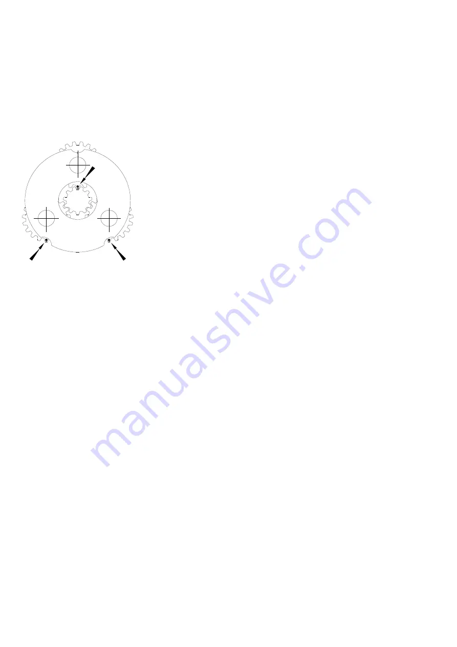
(18) , check for good indexing of planet gears
and repeat the above operation if necessary.
(Dwg.D6310013)
•
For correct assembly of planet gears, each planet
gear must be positioned with the timing mark as shown
on drawing D6310013.
1.8.
Install the spring washer (49) and the output
annular gear (50).
1.9.
Assembly of the box cover
−
Install the oil seal (52) and the bearing (51
and 53).
−
Install the output shaft (5) with the
retainer ring (54) in the gear box cover.
−
Install the 'O' ring (9).
−
Install the gear box cover ass'y and secure
with screws (47) and washers (48).
2.
Assembly of the brake piston
2.1.
Install the brake piston with the 'O' rings (23
and 25).
2.2.
Install bearing (36) , spring (41) and gasket
(33).
3.
Assembly of the front end cover.
3.1.
Clean the mounting front end cover (30) bore
and apply a bead of Loctite No.460 on the
backside of the oil seal (35).Install the oil
seal.
3.2.
Install the retainer ring (32).
3.3.
Install the front end cover (30) and secure
with screws (34).
4.
Install the three tie rod spacer (4) with the nuts (2)
and the washer (3).
5.
Fill up the brake with oil.
6.
Install the gasket (31) and the 'O' ring (27).
7.
Install the motor ass'y and secure with the four
screws.
8.
Position the winch vertically with the motor end
down.
9.
Fill up the gear box with oil SAE 80W90
−
kinematics viscosity 145 mm²/s at 40°C(104°F)
−
capacity of gear box : 0.13 gall (0.5 Litres)
10.
Drum assembly
10.1.
Scrape old Loctite from the drum bushing
bore and apply a bead of Loctite N°406 on
the smooth face of drum bushings (38).
10.2.
Install drum bushing in drum bushing bore by
taking care to adjust the gaps of the drum
bushing to 3.9 ins (100mm) do not allow any
clearance between drum bushings and drum.
10.3.
Lubricate drum bushings with grease.
10.4.
Install the drum on the gear box assembly.
10.5.
Lift out the drum to check for good
positioning of drum bushing
11.
Clutch control assembly (PS SERIES)
11.1.
Install plunger body (70) and plunger (61) on
the rear end cover (55) and secure with screw
(67) and washer (68).
11.2.
Install bearing (71) on clutch axle (66) with
retainer ring (65) and install the clutch (72)
with the retainer ring (62).
11.3.
Pull the plunger (61) to introduce the clutch
axle with the spring (69) into the plunger
body (70) and install the handle (65).
12.
Assembly of the rear end cover (55).
12.1.
Install bearing (58) on the rear cover.
12.2.
Install exhaust washers (69) with ring (59).
13.
Install spacer (64) on the output shaft (PS SERIES).
Install the rear end cover Ass'y on the three tie rod
(4) and secure with lock washers (3) and nuts (2).
Lever Control Valve Assembly
(Ref. Dwg.D6310006 or D6310035)
1.
Lubricate and install 'O' ring (125) on rotary valve
(126).
2.
Lubricate and carefully install rotary valve in valve
housing (122).
3.
Lubricate and install spring (124) on rotary valve.
Ensure pin (123) is installed in valve housing (122).
4.
Install stop (129). Apply a small amount of Loctite®
243 to threads of screws (127) and install.
5.
Install control handle (121) on rotary valve and align
pin hole. Install pin (128) to secure control handle.
&
Summary of Contents for LIFTSTAR
Page 11: ...11 NOTES...
Page 12: ...12 WINCH ASSEMBLY DRAWING Dwg D6310041...
Page 14: ...14 AIR GEAR MOTOR ASSEMBLY DRAWING Dwg D6310005...
Page 20: ...20 NOTES...
Page 22: ...22 TWO LEVER PENDANT ASSEMBLY DRAWING Dwg D5790002...
Page 31: ...31 NOTES...
Page 32: ...32 NOTES...
Page 33: ...33 NOTES...


