


n
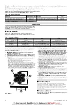
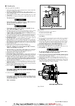
Live Air Throttle Valve
Refer to Dwg. MHP0203.
NOTICE
•
Match mark throttle valve parts to ensure proper reassembly.
1. Remove pins (428) and tap out pin (429) from handle bracket (426).
2. Mark the square end on the valve body (441) and the handle (426) to ensure
correct orientation during reassembly. Remove handle assembly.
3. Make note on how spring (427) is positioned before removing it. Remove
capscrews (444), lockwashers (443) and exhaust cover (442) from housing (438).
4. Remove pipe plug (434), spring (422), poppet valve (436) and ball (421) from
housing (438). Pull valve (441) out of the valve bushing (440).
5. Check parts for score marks or wear. Clearance between the valve bushing (440)
and valve (441) should not exceed 0.002 in. (0.05 mm) or excessive air leakage
will occur.
n
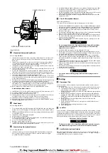
Manual or Automatic Band Brake
Refer to Dwg. MHP0209.
1. Automatic Brake:
a. Disconnect and remove hose, fittings and dump valve (112) from cylinder
(110).
b. Remove cotter pin (102) and pin (101) from link stud (103) and brake band
(128).
c. Remove cotter pin (102) and pin (106). Separate clevis (107) from brake lever
(105).
d. Remove cotter pin (102) and pin (117). Remove cylinder (110) from bracket
(118).
2. Manual Brake:
a. Remove cotter pin (102) and pin (101) from handle (104) then remove handle
(104) from brake band (128).
3. Remove capscrews (45), lockwashers (119) and stop plate (126). Ensure pivot
bracket (122) is no longer secured to siderail.
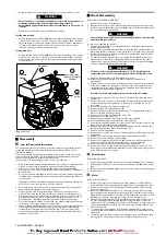
4. Use a hoist to raise winch approximately 6 inches (15 cm). Separate brake band
(128) halves and rotate brake band assembly slowly until it can be removed from
drum (80).
5. Remove cotter pins (102) and pins (121) so brake band halves (128) can be
removed from arm (124). Lower winch when brake band assembly has been
removed.
6. Refer to Product Parts Information Manual to order replacement parts.
n
Reduction Gear
NOTICE
•
It is important to maintain a clean work area when reduction gear assembly
is disassembled.
•
Disassembly is not recommended, if it is unavoidable, use the following
steps.
Refer to Dwg. MHP2773.
1. Place the reduction gear assembly on a clean work bench such that the end
containing seal (43) is down.
2. Remove capscrews (75) and pry off cover (73).
3. Remove four pins (74) from between cover (73) and spacer (71) and store in a
safe place.
4. Remove ring gear (72), sun gear (69) and planet assembly (67).
5. Remove ring gear (63) and spacer (71). Remove and discard ‘O’ rings (51) and
(62) from ring gears (63) and (72).
6. Remove capscrews (60) from the input housing (59).
7. Lift off input housing (59) and remove sun gear (66) from planet assembly (67).
8. If required, remove thrust plate (55) from sun gear (66).
9. Remove planet assembly (58) and sun gear (56).
10. Remove planet assembly (54) and ring gear (53).
11. Remove three dowel pins (52) from gear carrier (47) and store in a safe place.
12. Remove and discard ‘O’ rings (51) from ring gear (53).
13. Remove retainer ring (50) and bearing (49) from gear carrier (47).
n
Press Roller (optional feature)
Refer to Dwg. MHP2695.
1. Compress the ends of the springs (405) and (406) to disengage from siderail (82)
and pins on press roller arm (407).
CAUTION
•
Use care when releasing springs (405) and (406) from press roller. Springs
are under tension.
2. Loosen collars (404).
NOTICE
•
Ensure press roller assembly is adequately supported before removing
shaft (403).
3. Remove capscrews (408) and washers (409) from both ends of shaft (403), and
carefully slide shaft (403) through hole in upright (42). Press roller assembly (400)
and collar (404) will fall away from shaft (403).
4. It is not necessary to remove bushings (410) unless replacing.
5. Remove springs (405) and (406) from press roller arm (407).
6. Remove capscrews (408), washers (409) and rollers (402) from ends of press roller
arm (407).
n
Drum Locking Pin (optional feature)
Refer to Dwg. MHP2675.
1. Remove capscrews (305) and washers (306) to separate drum locking pin
assembly from winch upright (84).
2. Remove capscrew (313) from shaft (304). Separate washer (306), drum lock pin
(312) and housing (308) from assembly.
3. Remove nut (303) and capscrew (302) to separate handle (301) from shaft (304).
4. Remove bushing (311) from winch upright (84) only if replacement is required.
n
Cleaning, Inspection and Repair
n
Cleaning
Clean all winch component parts in solvent (except drum brake bands and disc brake
friction plates). The use of a stiff bristle brush will facilitate removal of accumulated
dirt and sediments in the reduction assembly, on housings, frame and drum. If drum
bushings have been removed it may be necessary to scrape old Loctite® from drum
bushing bores. Dry each part using low pressure, filtered compressed air. Clean drum
brake band using a wire brush or emery cloth. Do not wash drum brake band in
solvent. If drum brake band lining is oil soaked, it must be replaced.
n
Inspection
All disassembled parts should be inspected to determine their fitness for continued
use. Pay particular attention to the following:
1. Inspect all gears for worn, cracked, or broken teeth.
2. Inspect all bushings for wear, scoring, or galling.
3. Inspect shafts for ridges caused by wear. If ridges caused by wear are apparent
on shafts, replace shaft. Inspect all surfaces on which oil seal lips seat.
4. Inspect all bearings for play, distorted races, pitting and roller or ball wear or
damage. Inspect bearings for freedom of rotation.
5. Inspect all threaded items and replace those having damaged threads.
6. Inspect drum band brake lining for oil, grease and glazing. If drum band brake
lining is oil-soaked replace brake bands as a set. Remove glazed areas of band
brake lining by sanding lightly with a fine grit emery cloth.
7. Measure thickness of band brake lining. If brake band linings are less than 0.062
inch (2 mm) thick anywhere along edges replace brake bands (128) as a set.
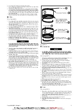
8. Inspect cylinder bores. Minor scratches in bore lining may be repaired by lightly
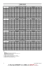
honing to remove. Refer to tolerances listed below for acceptable clearances.
Replace liner if deep scratches or gouges are apparent. Measure inside diameter
of liner. If measurement is greater than 4.764 inches (121 mm) replace liner. ‘Ring
Gap’ may also be used to determine wear; place compression ring into liner,
using a piston, push ring until approximately half way in liner and measure ‘Gap’
— 0.003 inch (0.076 mm) is normal; replace rings, or liner, if ‘Gap’ exceeds 0.020
inch (0.51 mm).
9. Inspect the drive plates for warpage or other damage, and replace damaged
parts as necessary. Replace the input pinion shaft oil seal.
10. Measure the thickness of the brake friction disc. The brake friction disc must
show an even wear pattern. If the brake friction disc is 0.076 in. (1.93 mm) or less,
replace the disc.
n
Repair
Actual repairs are limited to removal of small burrs and other minor surface
imperfections from gears and shafts. Use a fine stone or emery cloth for this work.
Do not use steel wool.
1. Worn or damaged parts must be replaced. Refer to the applicable Parts Listing
for specific replacement parts information.
2. Inspect all remaining parts for evidence of damage. Replace or repair any part
which is in questionable condition. Cost of the part is often minor in comparison
with cost of redoing job.
3. Smooth out all nicks, burrs, or galled spots on shafts, bores, pins, or bushings.
4. Examine all gear teeth carefully, and remove nicks or burrs.
5. Polish edges of all shaft shoulders to remove small nicks which may have been
caused during handling.
6. Remove all nicks and burrs caused by lockwashers.
7. Replace all gaskets, oil seals, and ‘O’ rings removed during winch disassembly.
n
Assembly
n
General instructions
•
Use all new gaskets and seals.
•
Replace worn parts.
•
Assemble parts using match marks attached during disassembly. Compare
replacement parts with originals to identify installation alignments.
•
Lubricate all internal parts with rust and oxidation inhibiting lubricant, ISO
VG 100 (SAE 30W).
•
Apply a light coat of Loctite® 243 to all threaded components prior to
assembly, unless otherwise specified.
n
Live Air Throttle Valve
Refer to Dwg. MHP0203.
NOTICE
•
During assembly align parts using match marks made during disassembly.
1. Install valve (441) and valve bushing (440) into the housing (438).
2. Install ball (421), poppet valve (436), spring (422) and pipe plug (434) in housing
(438).
3. If screws (430) were removed during disassembly, reinstall in housing (438) and
handle bracket (426).
8
Form MHD56303 Edition 2


