


1. Attach test load of desired weight to load line, or connect load line to scale.
WARNING
•
Ensure load line is connected to load and excessive slack is taken up before
activating auxiliary valve. When activated, auxiliary valve will
automatically engage and winch will operate at full speed to set tension on
load line.
2. With winch control valve remove all slack from load line.
Setting with test load:
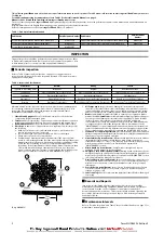
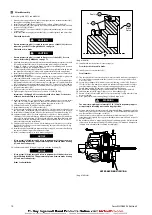
1. Actuate auxiliary valve to TENSIONING position. Winch should operate, causing
load line to become taut. To increase tension, rotate regulator knob clockwise
until load begins to rise. Rotate regulator knob counterclockwise a minimum of
1/4 turn, or until load is balanced (does not raise or lower). Note pressure
indicated on gauge for future setting reference.
Setting with scale:
1. Actuate auxiliary valve to TENSIONING position. Winch should operate, causing
load line to become taut. To increase tension, rotate regulator knob clockwise
until scale indicates desired tension. Note pressure indicated on gauge for future
setting reference.
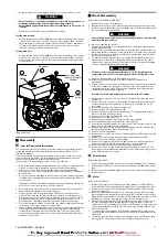
Position)
Regulator
Pressure
Gauge
C
D
Auxiliary Valve
(shown in Normal
Position)
Control
Valve
B
A
(Dwg. MHP1865)
n
Disassembly
n
General Disassembly Instructions
The following instructions provide necessary information to disassemble, inspect,
repair, and assemble product. Parts drawings are provided in Product Parts
Information Manual.
If a product is being completely disassembled for any reason, follow the order of
topics as they are presented. It is recommended that all maintenance work on
product be performed in a clean dust-free work area.
In the process of disassembling product, observe the following:
1. Never disassemble product any further than is necessary to accomplish needed
repair. A good part can be damaged during the course of disassembly.
2. Never use excessive force when removing parts. Tapping gently around
perimeter of a cover or housing with a soft hammer, for example, is sufficient to
break the seal.
3. Do not heat a part with a flame to free it for removal, unless part being heated
is already worn or damaged beyond repair and no additional damage will occur
to other parts.
In general, products are designed to permit easy disassembly and assembly. The
use of heat or excessive force should not be required.
4. Keep work area as clean as practical, to prevent dirt and other foreign matter
from getting into bearings or other moving parts.
5. All seals, gaskets and ‘O’ rings should be discarded once they have been
removed. New seals and ‘O’ rings should be used when assembling product.
6. When grasping a part in a vise, always use leather-covered or copper-covered
vise jaws to protect the surface of part and help prevent distortion. This is
particularly true of threaded members, machined surfaces and housings.
7. Do not remove any part which is a press fit in or on a subassembly unless removal
of that part is necessary for repairs or replacement.
8. When removing ball bearings from shafts, it is best to use a bearing puller. When
removing bearings from housings, drive out bearing with a sleeve slightly
smaller than outside diameter of bearing. The end of sleeve or pipe which
contacts bearing must be square. Protect bearings from dirt by keeping them
wrapped in clean cloths.
n
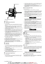
Winch Disassembly
Refer to Dwgs. MHP0210 and MHP2773.
1. Remove the wire rope from the drum.
2. Operate the winch to position reduction gear drain plug at its lowest position.
3. Relieve pressure in the air lines by operating the winch control several times after
the air supply has been turned off.
WARNING
•
Shut off, bleed down and disconnect the air supply line before performing
any disassembly procedures.
4. Disconnect and tag the air lines.
5. Remove the winch from its mounting and take to a suitable work area before
beginning disassembly.
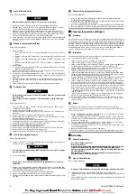
6. Remove lower case drain plug (464) in motor housing (463) and allow the oil to
drain into a suitable container. Loosen fill cap (462) to vent the motor housing.
7. Drain oil from the gear reduction assembly by removing pipe plug (48) when
positioned at its lowest point.
8. For winches with a disc brake remove pipe plug (25) in brake housing (17) to
drain brake oil. If the winch is equipped with a drum band brake the winch
outboard end (opposite the motor end) must be elevated to prevent draining
oil from contaminating the brake band lining.
WARNING
•
The FA2i air motor weighs approximately 117 lb. (53 kg). Adequately
support the air motor before removing the motor mounting capscrews.
9. Remove winch guard. Refer to ‘Winch Guard’ on page 7.
10. Remove drum band brake and any other externally mounted winch
attachments.
11. Remove the capscrews (97) and lockwashers (96) securing the motor assembly
to the motor adapter (6). Using a hoist to support the motor, pull the motor
straightaway from the winch. Reference the applicable Motor Disassembly
section if motor disassembly is required.
Instructions 12 through 18 apply only to winches with a disc brake.
12. Alternately and evenly loosen capscrews (93). Remove capscrews and motor
adapter (6).
13. Remove the brake housing (17). If the brake housing sticks, tap it with a brass
hammer until the pieces separate. Note the position of all brake pieces for
reassembly.
14. Remove friction plates (19) and drive plates (18).
15. Remove springs (9) from brake piston (10).
16. Remove brake piston (10) from brake housing (17). Tap lightly with a plastic
mallet to separate parts if necessary.
17. Remove seals (11) and (12) from brake piston (10).
18. Remove gear (21) from shaft (35).
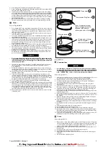
19. Remove retainer ring (36) from the bore of the drum shaft (41).
20. Pull shaft and bearing assembly from the drum shaft (41).
21. Support the drum (80) and remove capscrews (39) from the drum shaft (41). Pry
drum shaft (41) from the inboard upright (42).
22. Remove capscrews (85) and lockwashers (98) which secure the siderails (82) to
the inboard upright (42). Drive out dowel pins (86).
23. Remove inboard upright (42).
24. Remove end cover (95), capscrews (97) and lockwashers (96) from the outboard
upright (84).
25. Remove capscrews (94) and bearing retainer (92) from the drum (80).
26. Remove drum and reduction gear assembly.
27. Remove the remaining capscrews (85) and lockwashers (98) that attach the
siderails (82) to the outboard upright (84). Drive out dowel pins (86).
28. Remove bearing (86) and seal (99) from outboard upright (84).
29. Remove capscrews (45) and lockwashers (46) from the gear carrier (47). Lift
reduction gear assembly from the drum (80). To disassemble reduction gear refer
to the ‘Reduction Gear’ on page 8.
n
Winch Guard
Refer to Dwg. MHP2676.
1. Remove capscrews (90) and washers (91) securing lifting lugs (83) to uprights.
2. Remove panels (805) one section at a time, by removing nuts (804) and crossbars
(806).
3. Remove capscrews (809) and washers (96) that secure frames to winch uprights
4. Remove frames.
n
Motor
Refer to Dwg. MHP0210.
1. Remove capscrews (364), lockwashers (96) and exhaust cover (469). Pull out
rotary valve (467) and rotary valve bushing (466). Remove adapter valve (468
2. Remove the capscrews (451), lockwashers (452) and cylinders (453) from the
motor housing (463).
3. Rotate the crankshaft assembly (473) to bring each wrist pin (457) above the
motor housing (463), then push out the wrist pin (457) and remove piston (455).
Plugs (456) pressed into ends of wrist pins (457) should not be removed. To avoid
breakage use extreme care when removing compression rings (454).
4. Pull the crankshaft assembly (473) with attached connecting rods (459) out of
the motor housing (463) by shifting the connecting rods (459) to clear the
cylinder holes. The connecting rods (459) are joined through a common journal
on the crankshaft and are held in place by connecting rod rings (474) on each
side of the main rib.
5. To remove the connecting rods (459) from the crankshaft (473), take out set
screw (478) and drive out the taper pin (479) securing the counterbalance to the
crankshaft.
6. Loosen the capscrew (480), remove counterbalance, then pull off connecting
rod rings (474), connecting rods (459), bushing (476) and sleeve (475).
Form MHD56303 Edition 2
7


