


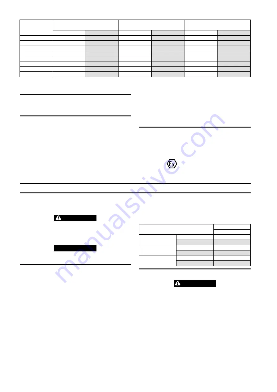
Layer
Line Speed @ 150 kg (330 lb) Load
Minimum Load for Emergency Lowering
Wire Rope Storage Capacity **
12 inch (305 mm) Drum
fpm
mpm
lb
kg
ft
m
1
82
25
200
91
86
26
2
85
26
187
85
178
54
3
87
26.5
176
80
275
84
4
89
27
166
75
378
115
5
91
27.7
158
72
487
148
6
93
28.3
150
68
602
183
7
94
28.6
140
64
723
220
8 (1)
95
29
136
62
849
259
** Wire rope storage capacity based on DNV and NMD standards of 2.5 times wire rope diameter below drum flange. Wire rope storage capacities listed may vary from figures
stated elsewhere.
1. Full drum at rated operating pressure and line speed.
n
Capacity Information
FA150KGi Man Rider
™ winches are designed for lifting with a 5:1 minimum safety
factor at rated load.
n
Traceability
Load bearing parts are documented to provide traceability. Documentation includes
chemical and physical properties of raw material, heat treating, hardening, tensile
and charpy tests as required for the part.
Units with
M1
,
M2
or
M3
in the model code have traceable load bearing components.
M1
– Material Traceability certificates according to EN 10204 (Ex DIN 50049) 2.2 on
load bearing parts. Conformity documents affirm (by the manufacturer) that parts are
in compliance with requirements of the order, based on non-specific inspection and
testing (i.e. results are typical material properties for these parts).
M2
– Material Traceability certificates according to EN 10204 (Ex DIN 50049) 3.1b on
load bearing parts. Conformity documents affirm (by a department independent of
the manufacturing department) that actual parts are in compliance with requirements
of the order, based on specific inspection and testing (i.e. results are actual material
properties for these parts).
M3
– Material Traceability certificates according to EN 10204 (Ex DIN 50049) 3.1b on
load bearing parts. Conformity documents affirm (by a department independent of
the manufacturing department) that the actual parts used in the product are in
compliance with the order, based on specific inspection and testing (i.e. results are
actual material properties for these parts in a finished, as delivered condition).
Components with part numbers ending in CH are charpy parts for use under extreme
cold conditions. Traceability requirements must be stated when reordering these parts
for continued certification.
n
ATEX
Refer to labeling on product, located near or on data (name) plate, for specific ATEX
designation. Product not marked as such, are not suitable for use in any potentially
explosive atmosphere (ATEX). Refer to Product Safety and Maintenance Information
Manuals for further explanation.
II 2 GD c IIB 200°C X
(Dwg. MHP2584)
INSTALLATION
Winch gearbox and disc brake are supplied fully lubricated from factory. Check oil
levels and adjust as necessary before operating winch.
Refer to “LUBRICATION” section on page 9 for recommended oils. Prior to
installing winch, carefully inspect it for possible shipping damage.
CAUTION
• Owners and users are advised to examine specific, local or other regulations,
including American Society of Mechanical Engineers (ASME) and/or OSHA
Regulations which may apply to a particular type of use of this product before
installing or putting product to use.
NOTICE
• Prior to installation refer to Product Safety Information Manual.
n
Mounting
Care must be taken when moving, positioning or mounting winch. Winch has lifting
lugs bolted to both uprights to assist in moving the unit. Attach hooks or a suitable
sling to these lugs when moving winch. Refer to “SPECIFICATIONS” section
on page 3 to determine winch weight.
Mount winch so drum axis is horizontal and motor control valve pad is not more than
15 degrees off top vertical center. If winch is to be mounted in an inverted position,
the motor case must be rotated to position control valve pad at the top and adequate
clearance must be provided for control valve operation. Position winch to provide
unrestricted access to winch control valve. Do not mount winch in a vertical position,
with motor up or down. Reduction gear box lubrication is not designed for this type
of installation.
1. Winch mounting surface must be flat and of sufficient strength to handle rated
load plus the weight of the winch and attached equipment. An inadequate
foundation may cause distortion or twisting of the winch uprights and side rails
resulting in winch damage.
2. Make sure mounting surface is flat to within 1/16 inch (1.6 mm). Shim if
necessary.
3. Mounting bolts must be 5/8 inch NC (16 mm) Grade 8 or better. Use self-locking
nuts or nuts with lockwashers. Refer to Table 3 ‘Mounting Bolt Hole
4. Tighten mounting bolts evenly. Refer to “Torque Chart” in Product Maintenance
Information Manual for proper tightening values.
5. Maintain a fleet angle between lead sheave and winch of no more than 1-1/2
degrees. The lead sheave must be on a center line with the drum and, for every
inch (25 mm) of drum length, be at least 1.6 ft (0.5 m) from the drum. Refer to
Product Safety Information Manual.
Refer to Dwg. MHP2288 on page 11,
A.
Drum.
Table 3: Mounting Bolt Hole Dimensions
Dimension
Drum Length (inches)
12
“A”
inch
20
mm
508
“B”
inch
9
mm
229
“C”
inch
0.69
mm
18
n
Wire Rope
CAUTION
• Maintain at least 3 tight wraps of wire rope on the drum at all times.
• Do not use wire rope as a ground (earth) for welding.
• Do not attach a welding electrode to winch or wire rope.
• Install wire rope to come off drum for underwound operation (normal
application). Refer to Product Safety Information Manual.
Install winch so wire rope, when at take-off angle limits, does not contact mounting
surface or drum guard panels. Install winch with single part wire rope reeving only.
Refer to Dwg. MHP3149 on page 11.
A.
Adjust slack arm prior to use, for wire rope
take-off angle.
n
Wire Rope Selection
Consult a reputable wire rope manufacturer or distributor for assistance in selecting
the appropriate type and size of wire rope and, where necessary, a protective coating.
Use a wire rope which provides an adequate safety factor to handle the actual working
load and meets all applicable industry, trade association, federal, state and local
regulations.
4
Form MHD56470 Edition 4


