background image

2–2

FAILURE TO OBSERVE THE FOLLOWING WARNINGS COULD RESULT IN INJURY.

USING THE TOOL (Continued)

Do not remove the Inlet Plug without first discon-
necting the live air supply.

Whenever the Angle Head is installed or reposi-
tioned, the Throttle Lever  must be positioned so
that reaction torque will not tend to retain the
throttle in the “ON” position.

When installing or removing the output device on
any tool, ALWAYS grasp a metal component of
the tool while tightening or loosening the Coupling
Nut or Spindle Cap.  Acceptable clamping 
locations include, but are not limited to, the hex on
the Gear Case, the Tool Hanger, the Torque Reac-
tion Arm or any metal Mounting Plate.  NEVER
grasp the composite tool body or handle in vise
jaws to restrain the torque of the Coupling Nut or
Spindle Cap.  Such practice will result in damage
to the tool.

Do not use power units and gear trains that exceed
the capability of the output device.

The Tube Nut Attachment has an opening on 
the front side for construction and application
purposes.  DO NOT, under any circumstance
place your fingers in this opening.

The Torque Reaction Bar must be positioned
against a positive stop.  Do not use the Bar as a
dead handle and take all precautions to make 
certain the operator’s hand cannot be pinched
between the Bar and a solid object.

When operated continuously for long periods of
time, Series D Nutrunners may become hot at the
spindle end of the tool.  Take all precautions 
necessary to avoid skin contact with the hot 
surfaces.  Prolonged contact may result in burns.

All Series D Torque Control Wrenches and 
Nutrunners with reverse capability have rotation-
al arrows molded into the housing in the area of
the reversing mechanism.  When the direction
switching device is positioned nearest the molded
circular arrow with an “F” in the center, spindle
rotation will be forward or clockwise direction.
When the direction switching device is positioned
nearest the molded circular arrow with an “R” in
the center, spindle rotation will be reverse or 
counterclockwise direction.

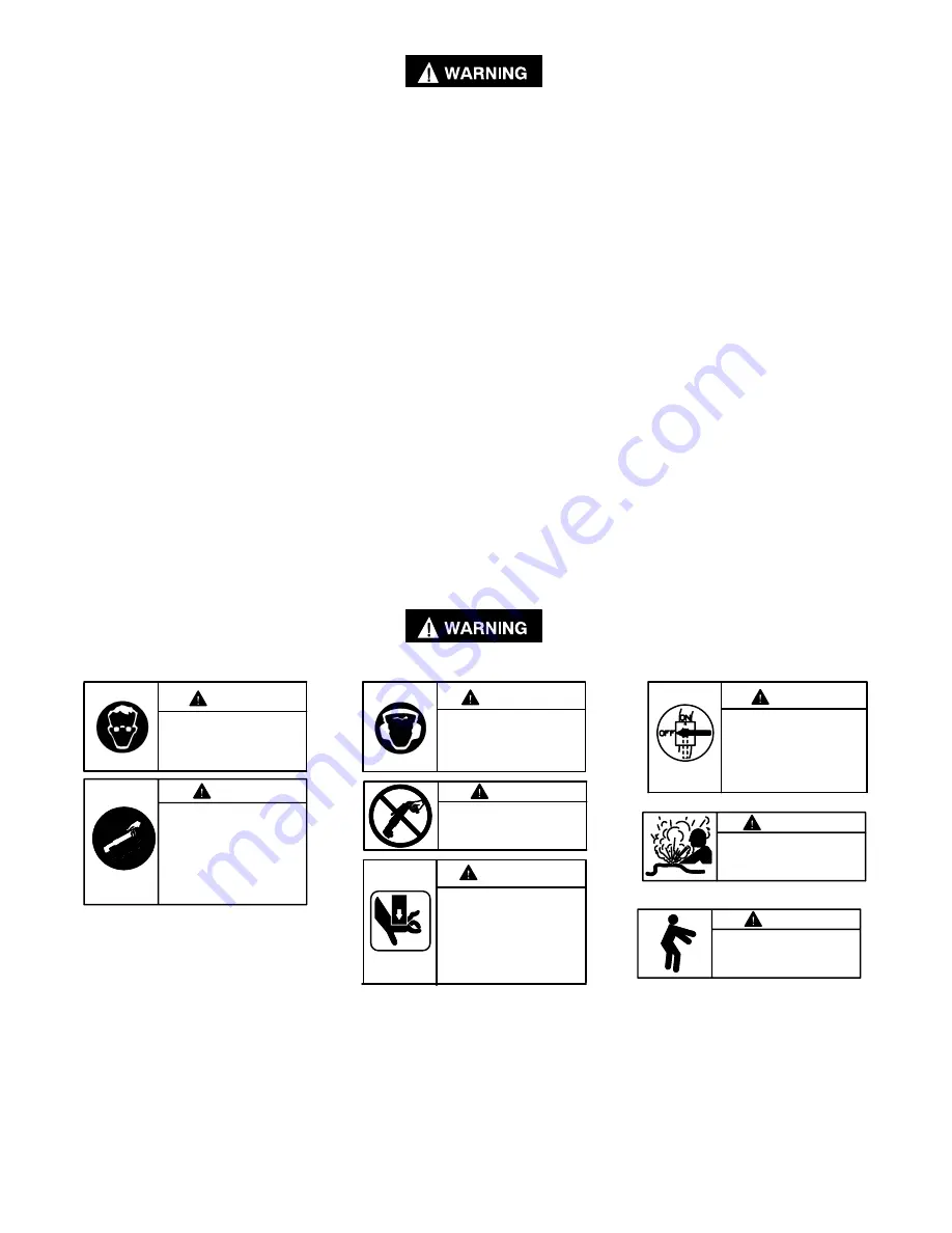
WARNING LABEL IDENTIFICATION

FAILURE TO OBSERVE THE FOLLOWING WARNINGS COULD RESULT IN INJURY.

Always wear eye protection
when operating or perform-
ing maintenance on this
tool.

WARNING

WARNING

Always wear hearing 
protection when operating
this tool.

Always turn off the electrical
supply and disconnect the
power cord before installing,
removing or adjusting any
accessory on this tool, or
before performing any 
maintenance on this tool.

WARNING

WARNING

Do not use damaged, frayed
or deteriorated power cords.

WARNING

Keep body stance balanced
and firm.  Do not overreach
when operating this tool.

WARNING

The Torque Reaction Bar must
be positioned against a 
positive stop.  Do not use the
Bar as a dead handle and take
all precautions to make certain
the operator’s hand cannot be
pinched between the Bar and 
a solid object.

Powered tools can vibrate in
use.  Vibration, repetitive mo-
tions or uncomfortable posi-
tions may be harmful to your
hands and arms.  Stop using
any tool if discomfort, tingling
feeling or pain occurs.  Seek
medical advice before resum-
ing use.

WARNING

Do not carry the tool by
the cord.

WARNING

Summary of Contents for DAA40 Series

Page 1: ... lubricate tools with flammable or volatile liquids such as kerosene diesel or jet fuel Do not remove any labels Replace any damaged label USING THE TOOL Always wear eye protection when operating or performing maintenance on this tool Always wear hearing protection when operating this tool Keep hands loose clothing and long hair away from rotating end of tool Note the position of the reversing lev...

Page 2: ...ntact with the hot surfaces Prolonged contact may result in burns All Series D Torque Control Wrenches and Nutrunners with reverse capability have rotation al arrows molded into the housing in the area of the reversing mechanism When the direction switching device is positioned nearest the molded circular arrow with an F in the center spindle rotation will be forward or clockwise direction When th...

Page 3: ...tor comfort Selection and adjustments should be made prior to placing the tool in service TOP REAR AIR INLET The air supply hose can be connected conventionally to the rear of the unit or connected to the side of the Handle if an over head air supply is available To change the inlet connection proceed as follows Do not remove the Inlet Plug 24 without first disconnecting the live air supply Do not...

Page 4: ...he Nut Lock and one of the notches in the Clutch Adjusting Nut 68 Insert the screwdriver far enough to create a gap between the Nut Lock and Adjusting Nut 4 Turn the screwdriver clockwise as you would to tighten a screw to increase the the clutch torque or counterclockwise to decrease the clutch torque 5 Final clutch adjustment should be set on the job GRIP ADJUSTMENT The Handle 1 of the Angle Wre...

Page 5: ...red grooves inside the Grip align with the appropriate lugs on the Handle Refer to TPD1257 Dwg TPD1257 4 Slide the Grip forward onto the Handle until it butts against the Collar Assembly 22 Refer to TPD1258 Dwg TPD1258 5 Push the Grip Latch downward to its original position to lock the adjustment into position Refer to TPD1259 Dwg TPD1259 ...

Page 6: ...2 6 Dwg TPA1537 1 ...

Page 7: ... DAA40 302 50 Housing Sleeve Assembly 19 Throttle Valve Seat DAA40 303 for models ending in EU DAA40 EU A39 20 Throttle Body DAA40 300 for all other models DAA40 A39 21 Throttle Body Seal 2 410 283 51 Warning Label 22 Collar for models ending in EU DAA40 703 for models ending in EU EU 99 22 Collar Assembly DAA40 A703 for all other models DAA40 99 23 Warning Label DAA40 98 52 Clutch Adjusting Hole ...

Page 8: ...2 8 Dwg TPB1019 ...

Page 9: ...ff Ball 6 DAA40 629 77 Cam Pin 3 DAA40 704 78 Cam Shaft DAA40 502 79 Cam Block DAA40 721 80 Clutch Spindle for DAA models DAA40 584 for DAAT models DAMT40 584 81 Spindle Retainer 7L1B 28 82 Clutch Bearing R1602 510 83 Drive Shaft Bearing R1602 510 84 Clutch Housing DAA40 580 DAA40 580 When replacing the Clutch Assembly or any clutch components check the gap of the Shutoff Valve Assembly as instruc...

Page 10: ...76 insert the shaft of the Shutoff Spool into the end of the Cam Shaft to prevent the Balls from becoming lodged in the central opening Position one of the shutoff ball openings downward and sharply rap the Cam Shaft on a work bench mat or a piece of corrugated cardboard box Two Shutoff Balls are installed in each hole Repeat the process at the other two locations for the remain ing four Balls Dis...

Page 11: ...ads of the slotted end of the Bushing 9 Using a screwdriver in the slot of the Bushing thread the assembled Plunger and Bushing into the Handle until the trailing end of the Bushing is flush with the handle surface Make certain the Plunger enters the hole in the Throttle Valve Guide Make certain the Plunger is retracted against the Bushing before instal ling the Throttle Valve Spring 16 10 Install...

Page 12: ... the Clutch Shaft Insert a 1 Phillips head screwdriver into the notch of the Nut Lock and one of the notches in the Nut Insert the screwdriver far enough to create a gap between the Nut Lock and Adjusting Nut Turn the screwdriver clockwise as you would to tighten a screw to move the Nut along the Shaft until it clears the groove for the Clutch Adjusting Nut Stop 67 9 Insert the jaws of snap ring p...

Page 13: ...bly will require adjustment To determine if the gap is correct remove the Motor Clamp Spacer 32 insert the Shutoff Valve Assembly 31 shaft first into the central opening of the motor assembly and measure the distance with a depth micrometer Refer to Dwg TPD1251 Dwg TPD1251 If the gap is incorrect proceed as follows a Remove the Valve Assembly from the motor b Place a wrench on the square of the va...

Page 14: ...rt buildup Clean and lubricate the motor unit parts Incorrect gap in Shutoff Valve Assembly Adjust the gap as explained in the section ASSEMBLING THE MOTOR TO THE HANDLE Leaky Throttle Valve Worn Throttle Valve and or Throttle Valve Seat Install a new Throttle Valve and or Throttle Valve Seat Dirt accumulation on Throttle Valve and or Throttle Valve Seat Pour about 3 cc of a clean suitable cleanin...

Page 15: ...2 15 NOTES ...

Reviews: