background image

651785 (en) 

Page 5 of 8

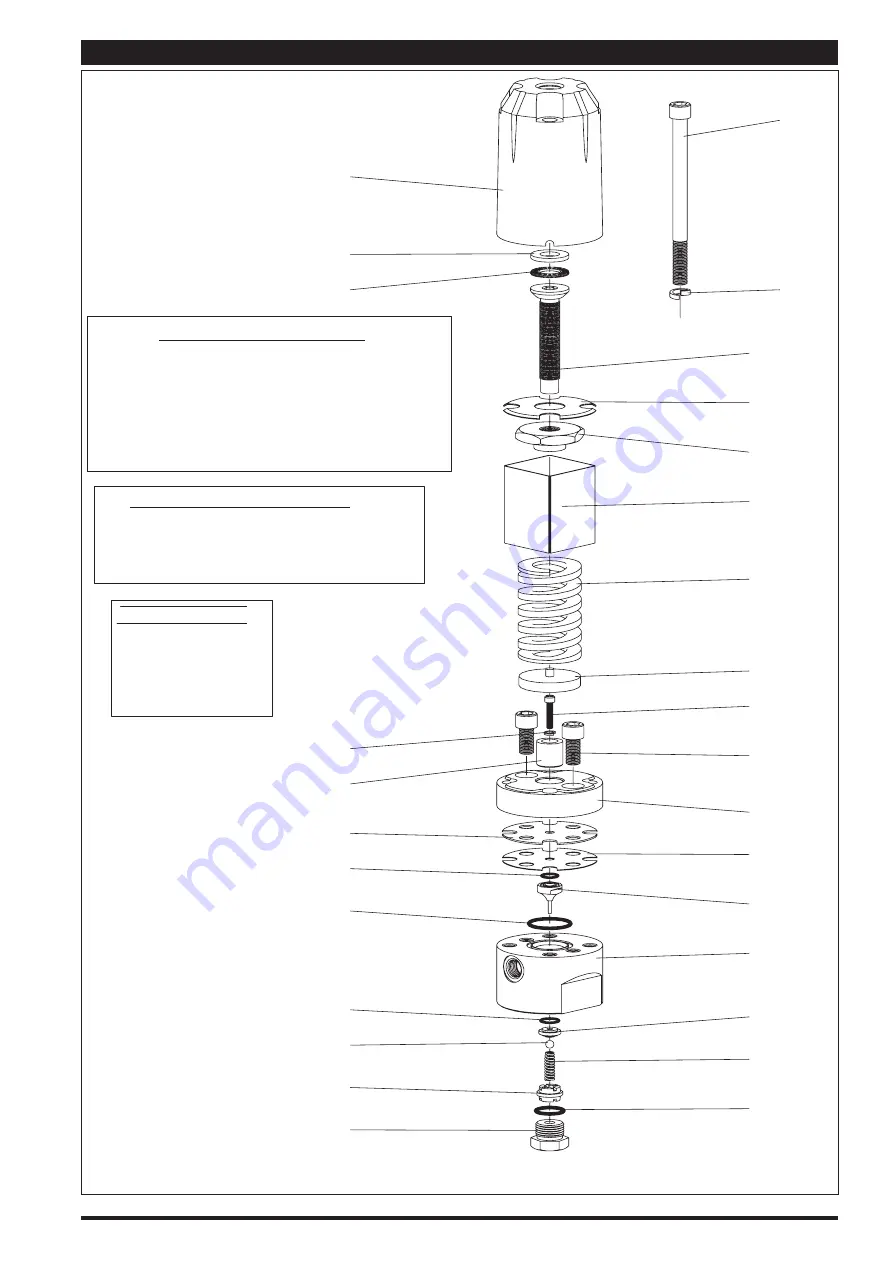
Figure 6

.

TORQUE REQUIREMENTS

,

(1) Bolt, torque alternately. First torque snug, then

to 20 - 25 ft lbs (27.1 - 33.9 Nm).

(12) Cap screw 65 - 75 in. lbs (7.3 - 8.5 Nm).

(15) Cap screw, torque alternately. First torque snug,

then to 20 - 25 ft lbs (27.1 - 33.9 Nm), then 50 - 55

ft lbs (67.8 - 74.6 Nm).

¡

Apply Dri-Slide upon assembly.

©

Apply Loctite nickel anti-seize to threads.

¢

Apply Loctite 242 to threads.

£

Apply 40036 grease.

LUBRICATION -- SEALANTS

28

27

26

25

24

23

22

21

18

16

15

, ¢

13

12

,

10

9

8

£

6

£

2

1

, ©

NOTE: DO NOT OVERTIGHTEN FASTENERS.

3

4

£

5

7

11

¡

14

17

19

20

29

MATERIAL CODE

[C] = Carbon Steel
[H] = Hytrel
[SS] = Stainless Steel
[T] = PTFE
[TC] = Tungsten Carbide
[ZA] = Zinc / Aluminum Alloy

PARTS VIEW / 651785 REGULATOR

Summary of Contents for 651785

Page 1: ...6 800 495 0276 FAX 800 892 6276 2017 CCN 47522184001 arozone com SERVICE KITS y y Use only genuine AROR replacement parts to assure compatible pressure rating and longest service life y y Fluid diaphragm kit 61962 1 can be ordered separately see page 4 SPECIFICATIONS Model Series 651785 Type Downstream Material Inlet female 3 8 18 NPTF 1 Material Outlet female 3 8 18 NPTF 1 Dimensional Data see pa...

Page 2: ... use Whenpumping flushing or recirculating volatile solvents be certain the area is adequately ventilated CAUTION FLUSH SUPPLY LINE Before installing fluid regulator blow the supply lines clear and flush to remove contaminates OPERATING AND SAFETY PRECAUTIONS INSTALLATION y y Refer to the typical installation view which best applies y y Locate the regulator as close as possible to the spray gun or...

Page 3: ...Y HAZARD MAINTENANCE y y Disassembly should be done on a clean work bench and use clean cloths y y If replacement parts are necessary refer to the parts list and drawings on pages 4 and 5 y y Upon reassembly lubricate parts and use Loctite where indicated Follow the torque specifications as shown y y Service kits are available which include parts typically needed for an overhaul y y Keep good reco...

Page 4: ...ite diaphragm onto the stem assembly first 4 Assemble the 14 piston to the stem assembly 5 Align the notches in the diaphragms and secure the assembly with the 13 lock washer and 12 cap screw NOTE Tighten 12 cap screw to 65 75 in lbs 7 3 8 5 Nm SERVICE HINT Use the 15 cap screw to help align the diaphragms 6 Remove the assembly from the vise 7 Place the 22 base in a vise clamping on flats 8 Place ...

Page 5: ...bs 27 1 33 9 Nm then 50 55 ft lbs 67 8 74 6 Nm Apply Dri Slide upon assembly Apply Loctite nickel anti seize to threads Apply Loctite 242 to threads Apply 40036 grease LUBRICATION SEALANTS 28 27 26 25 24 23 22 21 18 16 15 13 12 10 9 8 6 2 1 NOTE DO NOT OVERTIGHTEN FASTENERS 3 4 5 7 11 14 17 19 20 29 MATERIAL CODE C Carbon Steel H Hytrel SS Stainless Steel T PTFE TC Tungsten Carbide ZA Zinc Aluminu...

Page 6: ...Page 6 of 8 651785 en Figure 7 CROSS SECTION ...

Page 7: ...651785 en Page 7 of 8 DIMENSIONAL DATA Figure 8 3 7 32 81 7 mm 1 3 32 27 8 mm 7 27 32 198 8 mm 1 11 16 42 8 mm 2 5 16 58 7 mm 1 4 20 UNC 2B 2 Flow Direction Marking ...

Page 8: ...Page 8 of 8 651785 en ...

Reviews: