Page 2 of 8
651785 (en)
Y
Read and heed all Warnings and Safety Precautions
before operation of this unit.
Y
Use only genuine ARO replacement parts to assure
compatible pressure rating and longest service life.
Y
Be certain anyone operating this equipment or fluid
system has been trained to use it safely.
WARNING
HIGH PRESSURE DEVICE. IMPROPER
USAGE OF THIS EQUIPMENT COULD RESULT IN
SERIOUS INJURY. The possibility of injection into
the flesh is a potential hazard. Wear approved
safety glasses or face shield and other equipment as
needed to prevent injury. Never allow any part of the
human body to come in front of or in contact with
the material outlet, the tip, or the material outlet
of the dispensing device. An injection injury can be
serious. If an injection accident should occur, it is very
important that you contact a qualified physician for
immediate treatment.
WARNING
MISAPPLICATION HAZARD. DO NOT USE
THE REGULATOR WHEN THE FLUID INLET PRESSURE
IS TOO HIGH FOR THEDESIGNED OPERATING RANGE.
Excessive inlet pressure can cause a Lock-Out
situation. Lock-Out occurs whenthe inlet pressure
isbeyondthe regulator’s springcapacity. THE
VALVE WILL NOT OPEN. Attempts to disassemble
componentswhile in a Lock-Out condition mayresult
in injury.
WARNING
COMPONENT RUPTURE. DO NOT OPERATE
REGULATOR AT AN INLET PRESSURE GREATER THAN
SPECIFIED. To avoid possible damage or personal
injury, DO NOT operate this unit at pressure higher
than the stated operating range as it appears on the
model plate.
WARNING
D I S A S S E M B LY H A Z A R D. D O N OT
DISASSEMBLE THIS REGULATOR WHEN IT IS UNDER
PRESSURE. RELIEVE PRESSURE IN THE PUMPING SYSTEM
BEFORE ATTEMPTING SERVICE OR DISASSEMBLY
PROCEDURES. Disconnect air lines and carefully bleed
pressure off the system. Be certain the system is not
maintaining pressure due to amaterial restriction in the
hose, line, dispensing device, or the spray or extrusion
tip. Failure to relieve pressure both up stream and
downstream may result in an injury upon disassembly.
WARNING
BONNET REMOVAL HAZARD. DO NOT
ATTEMPT TO REMOVE THE FOUR BONNET RETAINING
BOLTS WITHOUT FIRST RELIEVING THE TENSION ON THE
MAIN SPRING. Failure to relieve tension could result in an
accident upon disassembly.
WARNING
PREVENT FIRES. KEEP SOLVENTS AWAY
FROM HEAT, SPARKS OR OPEN FLAME. Keep containers
closed when not in use.Whenpumping, flushing or
recirculating volatile solvents, be certain the area is
adequately ventilated.
CAUTION
FLUSH SUPPLY LINE. Before installing
fluid regulator, blow the supply lines clear and flush
to remove contaminates.
OPERATING AND SAFETY PRECAUTIONS
INSTALLATION
y
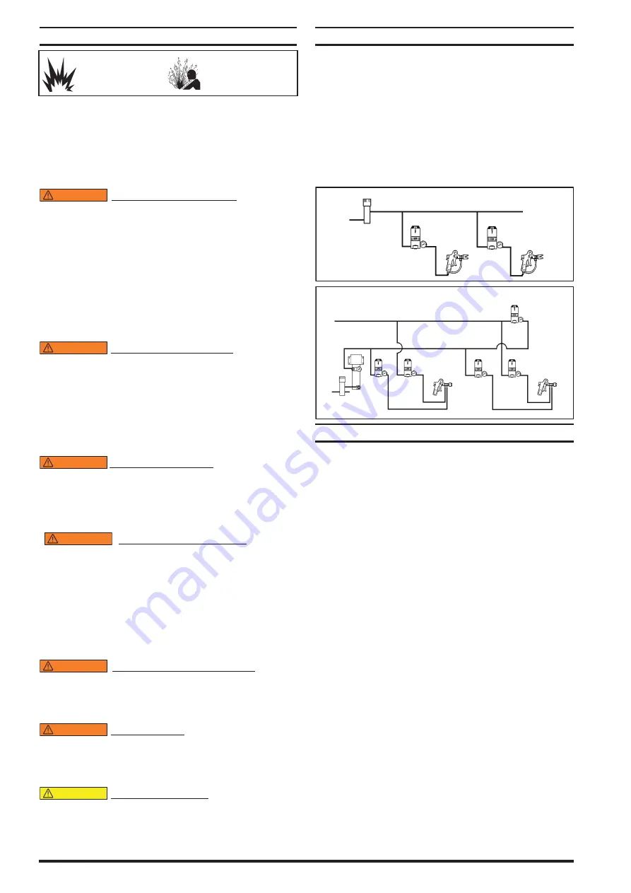
Refer to the typical installation view which best applies.
y
Locate the regulator as close as possible to the spray gun
or dispensing device for best pressure control.
y
Identify the regulator INLET / OUTLET (flow direction).
The regulator is marked with an arrow on the body base
(see figure 8).
y
When flexible fluid lines are used, mount the regulator
securely using the (2) 1/4” - 20 threaded holes in the base
(see figure 8).
y
Flush supply line before installing regulator.
TYPICAL DEAD END SYSTEM
Filter
Down Stream
Regulator
Down Stream
Regulator
Figure 2
Figure 3
TYPICAL RECIRCULATING SYSTEM
Back Pressure
Regulator
Back Pressure
Regulator
Filter
Heater
Back Pressure
Regulator
Down
Stream
Regulator
Down
Stream
Regulator
OPERATING INSTRUCTIONS
Refer to page 4 and 5 for parts reference.
y
To INCREASE outlet pressure, turn the (6) adjusting screw
CLOCKWISE (see figure 4).
y
To DECREASE outlet pressure, turn the (6) adjusting
screw COUNTERCLOCKWISE (see figure 4).
NOTE: ARO Part Y106-109 Allen wrench is included to make
necessary pressure adjustments.
FLUSH-OUT FEATURE (see figure 5).
y
Flush the regulator periodically. The interval may vary de-
pending on the amount and type of material used.
y
By using a wrench and “flush-out” plug (provided), the
operator is able to move the entire spindle downward
and force the ball off the seat which should purge the
regulator of particle build-up.
NOTE: The flush-out procedure temporarily overrides the
adjusted pressure. It will not, however, affect the regulator
setting when flushing operation is completed.
FLUSH-OUT PROCEDURE
1. Remove spray gun or dispensing device, this will allow
any particles to clear from the system.
2. Insert (30) flush-out plug and turn clockwise until it
touches the (4) washer (see view on page 5).
3. Turn up to two turns maximum. This will allow the ball
to unseat and pass material at free flow (unregulated).
DO NOT attempt to turn further to avoid damage.
4. Turn the plug back to its original position.
SEAT PLUG FEATURE
The (29) plug located at the base of the regulator can be
removed for access to the ball and seat assembly for clean-
ing and inspection for wear. With this feature, the regulator
EXCESSIVE AIR PRESSURE
STATIC SPARK
HAZARDOUS MATERIALS
HAZARDOUS PRESSURE


