background image

23

HB Series Desiccant Dryer Models 150-8000

ingersollrandproducts.com

EL

ECTRICAL

ENCL

O

SUR

E

NE

MA 4

DE

SICCANT DRAIN PORT

TOWER PRE

SS

UR

E

GAUGE

38.50

(4) .56'' DIA. MTG. 

HOLE

S

1 1/2'' 

FPT 

AIR 

OU

TLET

CON

NECTION

L

DE

SICCANT FILL PORT

L

32.00

2.00

TYP

2.00

TYP

BLUE MOISTURE INDICATOR PILOT AIR FIL

TER

11.

19

67.8

7

60.25

C OF AIR 

INLET

10.25

34.00

C OF AIR OU

TLET

C OF AIR OU

TLET

1 1

/2'' FPT AIR 

INLET

CONN

ECTION

52.50

9.50

C OF AIR 

INLET

38.50

22.18

22.18

FACE OF AIR 

INLET

FACE OF AIR OU

TLET

11.

19

37.37

20.81

RE

LIEF V

ALV

E

L

L

CONTROLL

ER & 

DISPLAY PAN

EL

(SEE

 DETAIL)

*NOTES:

  1) MAXI

MUM

 WORKING PRESSURE - 1

50

 P.S.I.

   2) 

SAFE

TY RELIE

F VALVE SETTING - 1

65

 P.S.I

  3) PILOT AIR LINE NOT 

SHO

WN 

FOR CLARITY.

 4) ALL WIRING IS

 IN ACCO

RDAN

CE WIT

H T

HE


      NATIONAL ELECT

RICAL CODE'S LATES

T EDIT

ION.

CONTROLLER & D

ISPLAY

 P

ANE

L DETAI

L

POWE

R ON LIGHT

LE

FT TO

WE

R RE

GE

N LIGHT

LE

FT TO

WE

R DRYING LIGHT

RIGHT TOWER DRYING LIGHT

RIGHT TOWER RE

GE

N LIGHT

DRYE

R O

FF /

 ALARM LIGHT

PU

SH

 B

UTTONS

1) ON 2) O

FF

3) RESET 4) T

ES

T

5) SE

T

6) SELECT D

ISPLAY

7) ENTER 8) +/-

LCD DI

SPLAY

1/4'' MPT AU

TOMATIC

 DRAIN

CON

NECTION

1) DRYER ON/OF

F C

ONTROL

2) DRYER 

AL

ARM

3) HEATER OPER

ATION & TE

M

P CONTROL

4) HIGH HEATER TE

M

P AL

ARM

5) HEATER FAILU

RE 

ALARM

6) LEF

T/RIGH

T T

OWER D

RYING

7) LEFT

/RIGHT 

TO

WER 

REGEN

8) FAILURE TO SHI

FT ALA

RM

9) REGEN SEQUENCE 

STATUS

10) BLO

WER OPERATION CONTROL

11) HIGH HUMIDIT

Y AL

ARM (O

PT

IONAL)

12) ENERGY MANAGEMEN

T SY

STEM

 (EM

S)

(OPT

IONAL

)

HEAT

ER O

N LIGHT

BLOWER ON LIGHT

1/4'' MPT AU

TOMATIC


D

RAIN CONNECTION

TOWER TEM

PE

RATUR

E

GAUGE

AFTE

RFILTER

PR

EFILTER

PURG

E ADJU

STM

ENT

PR

ES

SURE GAUG

E

OUTLET FLOW CHECK VALV

E

PURG

E FL

OW

CHECK VALV

E

BLOWER INTAKE FILTER

HE

AT

ER

REPR

ES

SURIZA

TION

VA

LVE

BLOWER P

RE

SS

UR

E

GAUG

E

PURGE FL

OW

CONTROL V

ALV

E

INLET FLOW 

VALV

E

PURGE V

ALV

E

DE

PR

ES

SURIZA

TION VAL

VE

BLOWER FL

OW

CONTROL V

ALV

E

D

EPR

ES

SURIZA

TION MUFFL

ER

28.00

.73

PILOT A

IR SHUT-OF

F

VA

LVE

OPTIONAL TO

WE

R INSULATION

(SH

OWN THIS VIEW ONLY)

45.50

FACE OF AIR 

INLET AND OUTLET

(OPTIONAL 3-VALV

E SKID B

YPAS

S)

12.12

FACE OF AIR 

INLET AND OUTLET

(OPTIONAL 3-V

ALV

E S

KID B

YPASS

)

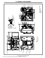
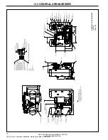
13.0 GENERAL ARRANGEMENT 

GENERAL

ARRANGEMENT

HB250-HB300

580465-A

120.26 Dryer - Operation, Installation, Maintenance Manual, and Parts 

Summary of Contents for 150-8000

Page 1: ... Manual Del Operador ES Manual do Operador PT Manuel De L opérateur FR Operator s Manual EN I R ORDER NUMBER 81696181 CUSTOMER NAME Woodward RCC c o ALL Equipment CUSTOMER CONTACT Kerry Fang 704 655 5364 CUSTOMER P O NUMBER 78608 DRYER MODEL HB3000 EMS 120 26 Dryer Operation Installation Maintenance Manual and Parts ...
Page 2: ...MBER 81696181 CUSTOMER NAME Woodward RCC c o ALL Equipment CUSTOMER CONTACT Kerry Fang 704 655 5364 CUSTOMER P O NUMBER 78608 DRYER MODEL HB3000 EMS 120 26 Dryer Operation Installation Maintenance Manual and Parts ...

Page 3: ... 1 FAILURE TO REPRESSURIZE 8 4 2 FAILURE TO DEPRESSURIZE CONTENTS PAGE 8 5 HIGH DEW POINT ALARM INCLUDED WITH EMS 8 6 ENERGY MANAGEMENT SYSTEM EMS OPTIONAL 8 7 ALARM LIST 8 8 HIGH OUTLET TEMPERATURE OPTIONAL 9 0 TECHNICIAN MODE 10 9 1 ENTERING TECHNICIAN MODE 9 2 OPERATING MODE 9 3 COOL SWEEP 9 4 HEATER TEMPERATURE SETPOINT BLOWER PURGE MODE ONLY 9 5 ENERGY MANAGEMENT SYSTEM OPTIONAL 9 5 1 ENABLIN...

Page 4: ...omplied with specific recommendations of the Company Accessories or equipment furnished by the Company but manufactured by others shall carry whatever warranty the manufacturers have conveyed to the Company and which can be passed on to the Purchaser The Company shall not be liable for any repairs replacements or adjustments to the Equipment or any costs of labor performed by the Purchaser or othe...

Page 5: ...ll main electrical disconnect switch and disconnect any separate control lines if used before attempting to work or perform maintenance on the unit 4 Do not attempt to service any part while machine is in an operational mode 5 Do not attempt to remove any parts without first relieving the entire air system of pressure 6 Do not operate the dryer at pressures in excess of its rating 7 Do not operate...

Page 6: ... heater and blower operate for 2 hours and 57 minutes The blower continues to operate for an additional ten minutes to cool the heater The Repressurization Valve is then opened allowing dry compressed air to pass through the regenerating tower for 48 minutes 7 0 PRINCIPLES OF OPERATION 7 3 3 HEATLESS PRESSURE SWING REGENERATION In the heatless mode following depressurization regeneration uses appr...

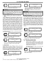
Page 7: ...corresponding values When power is supplied to the dryer the Microprocessor Control will illuminate and default to the Standby mode displaying the Press ON prompt The following illustration summarizes the keypad functions Figure 1 Microprocessor Controller BUTTONS ON Initiates PLC program Begins system monitoring and valve switching functions OFF Stops PLC program Stops valve switching functions I...

Page 8: ...E Indicates whether unit is currently consuming purging air Requires EMS Heater Status BLOWER PURGE MODE ONLY On Off Indicates that the heater is being given a signal to heat the purge air Blower Status BLOWER PURGE MODE ONLY On Off Indicates that the blower is being given a signal to supply the purge air Heater Temperature BLOWER PURGE MODE ONLY HEATER TEMP XX Indicates the heater temperature set...

Page 9: ...gram Should however power be cut to the dryer before the Shutdown Sequence has been initiated the dryer can be configured to restart in one of two restart modes 7 8 1 MANUAL MODE ZERO Ingersoll Rand dryers are shipped from the factory in the Manual Mode After power is re supplied to the dryer the user will be presented with the PRESS ON display The valve switching and timing operations will only s...

Page 10: ... point The EMS dew point sensor communicates the pressure dew point reading to the Microprocessor Controller Should the pressure dew point rise above the alarm set point the Microprocessor Controller will display the alarm condition on the controller screen 8 6 ENERGY MANAGEMENT SYSTEM EMS OPTIONAL EMS is an energy savings feature that matches moisture loading and regeneration energy usage Drying ...

Page 11: ...ollowing Depressing the button returns the controller to the top of the ALARM LIST BEGIN ALARMS Depressing the button again returns the controller to the CUSTOMER MODE ALARM LIST PRESS ENTER Depressing the SELECT DISPLAY list displays the most recent of the alarms stored by the Microprocessor Control Refer to the diagram at the end of this section for an explanation of the ALARM LIST Display FAIL ...

Page 12: ...COOL SWEEP COOL SWEEP OFF ON HEATER TEMPERATURE SETPOINT HEATER TEMP 300 425 ENERGY MANAGEMENT SYSTEM OPTIONAL EMS OFF ON ENERGY MANAGEMENT SYSTEM SETPOINT OPTIONAL EMS SET POINT 76 68 PURGE TEMPERATURE PURGE TEMP OFF ON RESTART MODE RESTART LAST ZERO EXTENDED HEATING EXTENDED HTG OFF ON HIGH DEW POINT ALARM ACTIVATION OPTIONAL HI DEW POINT OFF ON Pressing the 2 and 3 buttons simultaneously enters...

Page 13: ...5 ENERGY MANAGEMENT SYSTEM OPTIONAL The Energy Management System option includes a dew point sensor that transmits the outlet pressure dew point to the Microprocessor Controller The Microprocessor Controller displays the outlet pressure dew point in real time This option package also includes Energy Management System an energy savings feature that matches moisture loading and regeneration energy u...

Page 14: ...Depress the SELECT DISPLAY button until the START MODE screen is displayed RESTART ZERO SELECT DISPLAY RESTART LAST A NOTICE The restart modes will only effect restarting should power be unexpectedly removed from the dryer After proper shut down the dryer will require the user to depress the ON button to initiate the operation of the dryer program 9 8 EXTENDED HEATING OPTIONAL BLOWER PURGE MODE On...

Page 15: ...idered normal operation The Microprocessor Controller will only permit the jog function during specific stages of the program Should the program be at a stage where the program can not advance the following will be displayed Depress the SELECT DISPLAY button until the HIGH DEW POINT SET POINT screen is displayed HI PDP SETPOINT 10 SELECT DISPLAY SET Pressing the SET button permits the value of the...

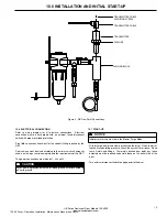
Page 16: ...es to the inlet and outlet connections Locate the pre filters as close as possible to the dryer Ensure the positioning allows for ease of servicing Note that the wet air inlet is located at the dryer s upper manifold and the dry outlet air is located at dryer s lower manifold In situations where air supply is required 24 hours a day it is undesirable to interrupt the airflow a three valve bypass s...

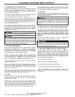
Page 17: ...ccording to the minimum circuit ampacity shown on the dryer serial nameplate and the requirements of the NEC The power connections are marked L1 L2 and L3 A CAUTION Dryer must be grounded with the full sized ground wire connected to an earth ground 10 7 START UP With dryer de energized slowly pressurize the dryer When the dryer reaches full operating pressure check the system for air leaks Soap te...

Page 18: ...ON Depress the ON button to initiate the dryer program The Microprocessor Controller will display the first CUSTOMER MODE screen LT DRY RT REGEN ON The sequence will initiate proper Inlet and Purge Valve positioning and tower depressurization If the dryer has been in storage or off for an extended period of time the Blue Moisture Indicator may be gray the High Dew Point Alarm if equipped may be ac...

Page 19: ...s often as required to prevent contamination of the regenerative dryer s desiccant bed Pre filter drains must be checked daily Failure to drain condensed liquid from the sump of the filter housing will result in carry over and damage to the desiccant material HB post filters are used to prevent desiccant dust particulate contamination from migrating downstream into plant processes Elements should ...

Page 20: ...GEOUT PROCEDURE A WARNING To avoid injury depressurize dryer before performing any service A CAUTION Be sure to wear respiratory protection during the draining and filling process to minimize inhalation of desiccant as desiccant will produce dust during this procedure A NOTICE Each dryer is shipped with a desiccant sample kit to allow the desiccant to be sent for analysis This kit can be used to h...

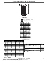
Page 21: ... 4 8 mm ACTIVATED ALUMINA 1 8 2 5 mm HB 3 16 4MM 8MM 1 8 2MM 5MM MODEL ACTIVATED ALUMINA LB ACTIVATED ALUMINA LB 150 52 184 200 78 266 250 100 298 300 111 359 400 160 444 500 178 570 600 86 922 800 86 1184 1000 142 1258 1200 142 1464 1500 266 1934 1800 266 2334 2100 266 2662 3000 572 3654 4000 720 4418 5000 896 6304 6000 1100 7540 8000 1400 10120 NOTE Qty is per dryer DESCRIPTION PART ACTIVATED AL...

Page 22: ...nt to heater and blower Correct problem and reset blower motor starter Remove and clean or replace blower filter Reset blower motor starter Replace control solenoid valve Reset blower motor starter Repair or replace valve Reset blower motor starter Replace check valve Reset blower motor starter Verify and correct sizing of exhaust piping Reset blower motor starter Insufficient purge rate I Inlet a...

Page 23: ... CONTROLLER DISPLAY PANEL SEE DETAIL 34 00 C OF AIR OUTLET 66 09 1 4 MPT AUTOMATIC DRAIN CONNECTION 1 4 MPT AUTOMATIC DRAIN CONNECTION 20 81 TOWER TEMPERATURE GAUGE REACTIVATION BLOWER OPTIONAL TOWER INSULATION SHOWN THIS VIEW ONLY PILOT AIR SHUT OFF VALVE 17 50 17 50 PREFILTER PURGE ADJUSTMENT PRESSURE GAUGE OUTLET FLOW CHECK VALVE PURGE FLOW CHECK VALVE BLOWER INTAKE FILTER HEATER REPRESSURIZATI...

Page 24: ... 36 50 1 23 HEATER ON LIGHT BLOWER ON LIGHT 1 DRYER ON OFF CONTROL 2 DRYER ALARM 3 HEATER OPERATION TEMP CONTROL 4 HIGH HEATER TEMP ALARM 5 HEATER FAILURE ALARM 6 LEFT RIGHT TOWER DRYING 7 LEFT RIGHT TOWER REGEN 8 FAILURE TO SHIFT ALARM 9 REGEN SEQUENCE STATUS 10 BLOWER OPERATION CONTROL 11 HIGH HUMIDITY ALARM OPTIONAL 12 ENERGY MANAGEMENT SYSTEM EMS OPTIONAL TOWER TEMPERATURE GAUGE OPTIONAL TOWER...

Page 25: ...RESET 4 TEST 5 SET 6 SELECT DISPLAY 7 ENTER 8 LCD DISPLAY 1 4 MPT AUTOMATIC DRAIN CONNECTION 1 DRYER ON OFF CONTROL 2 DRYER ALARM 3 HEATER OPERATION TEMP CONTROL 4 HIGH HEATER TEMP ALARM 5 HEATER FAILURE ALARM 6 LEFT RIGHT TOWER DRYING 7 LEFT RIGHT TOWER REGEN 8 FAILURE TO SHIFT ALARM 9 REGEN SEQUENCE STATUS 10 BLOWER OPERATION CONTROL 11 HIGH HUMIDITY ALARM OPTIONAL 12 ENERGY MANAGEMENT SYSTEM EM...

Page 26: ...TOWER DRYING LIGHT 1 DRYER ON OFF CONTROL 2 DRYER ALARM 3 HEATER OPERATION TEMP CONTROL 4 HIGH HEATER TEMP ALARM 5 HEATER FAILURE ALARM 6 LEFT RIGHT TOWER DRYING 7 LEFT RIGHT TOWER REGEN 8 FAILURE TO SHIFT ALARM 9 REGEN SEQUENCE STATUS 10 BLOWER OPERATION CONTROL 11 HIGH HUMIDITY ALARM OPTIONAL 12 ENERGY MANAGEMENT SYSTEM EMS OPTIONAL 56 50 82 41 C OF MOUNTING HOLE C OF MOUNTING HOLE L L 40 50 2 0...

Page 27: ...F VALVE 3 NPT AIR INLET CONNECTION 3 NPT AIR INLET CONNECTION C OF AIR INLET L TOWER TEMPERATURE GAUGE 39 75 FACE OF AIR OUTLET HEATER ON LIGHT BLOWER ON LIGHT 1 DRYER ON OFF CONTROL 2 DRYER ALARM 3 HEATER OPERATION TEMP CONTROL 4 HIGH HEATER TEMP ALARM 5 HEATER FAILURE ALARM 6 LEFT RIGHT TOWER DRYING 7 LEFT RIGHT TOWER REGEN 8 FAILURE TO SHIFT ALARM 9 REGEN SEQUENCE STATUS 10 BLOWER OPERATION CON...

Page 28: ...F AIR OUTLET L RELIEF VALVE 3 NPT AIR INLET CONNECTION 3 NPT AIR INLET CONNECTION C OF AIR INLET L TOWER TEMPERATURE GAUGE 39 75 FACE OF AIR OUTLET HEATER ON LIGHT BLOWER ON LIGHT 1 DRYER ON OFF CONTROL 2 DRYER ALARM 3 HEATER OPERATION TEMP CONTROL 4 HIGH HEATER TEMP ALARM 5 HEATER FAILURE ALARM 6 LEFT RIGHT TOWER DRYING 7 LEFT RIGHT TOWER REGEN 8 FAILURE TO SHIFT ALARM 9 REGEN SEQUENCE STATUS 10 ...

Page 29: ...E L L L L AFTERFILTER FACE OF AIR INLET OUTLET OPTIONAL 3 VALVE BYPASS BLOWER BLOWER INTAKE FILTER 79 50 PREFILTER BLOWER PRESSURE GAUGE NEMA 4 ELECTRICAL ENCLOSURE CONTROL BOX NEMA 4 ELECTRICAL ENCLOSURE POWER BOX CONTROLLER AND DISPLAY PANEL SEE DETAIL POWER ON LIGHT ALARM LIGHT CONTROLLER LCD DISPLAY CONTROLLER PUSH BUTTONS CONTROLLER AND DISPLAY PANEL DETAIL 1 ON 2 OFF 3 RESET 4 TEST 5 SET 6 S...

Page 30: ...NTAKE FILTER PREFILTER BLOWER PRESSURE GAUGE NEMA 4 ELECTRICAL ENCLOSURE CONTROL BOX NEMA 4 ELECTRICAL ENCLOSURE POWER BOX CONTROLLER AND DISPLAY PANEL SEE DETAIL POWER ON LIGHT ALARM LIGHT CONTROLLER LCD DISPLAY CONTROLLER PUSH BUTTONS CONTROLLER AND DISPLAY PANEL DETAIL 1 ON 2 OFF 3 RESET 4 TEST 5 SET 6 SELECT DISPLAY 7 ENTER 8 LEFT TOWER REGEN LIGHT BLOWER ON LIGHT HEATER ON LIGHT RIGHT TOWER R...

Page 31: ...NCLOSURE POWER BOX CONTROLLER AND DISPLAY PANEL SEE DETAIL POWER ON LIGHT ALARM LIGHT CONTROLLER LCD DISPLAY CONTROLLER PUSH BUTTONS CONTROLLER AND DISPLAY PANEL DETAIL 1 ON 2 OFF 3 RESET 4 TEST 5 SET 6 SELECT DISPLAY 7 ENTER 8 LEFT TOWER REGEN LIGHT BLOWER ON LIGHT HEATER ON LIGHT RIGHT TOWER REGEN LIGHT RIGHT TOWER DRYING LIGHT LEFT TOWER DRYING LIGHT 1 DRYER ON OFF CONTROL 2 DRYER ALARM 3 HEATE...

Page 32: ...KE FILTER BLOWER PRESSURE GAUGE NEMA 4 ELECTRICAL ENCLOSURE CONTROL BOX NEMA 4 ELECTRICAL ENCLOSURE POWER BOX CONTROLLER AND DISPLAY PANEL SEE DETAIL POWER ON LIGHT ALARM LIGHT CONTROLLER LCD DISPLAY CONTROLLER PUSH BUTTONS CONTROLLER AND DISPLAY PANEL DETAIL 1 ON 2 OFF 3 RESET 4 TEST 5 SET 6 SELECT DISPLAY 7 ENTER 8 LEFT TOWER REGEN LIGHT BLOWER ON LIGHT HEATER ON LIGHT RIGHT TOWER REGEN LIGHT RI...

Page 33: ... OUTLET REPRESSURIZATION VALVE BLOWER PRESSURE GAUGE 77 56 INLET FLOW VALVE TYP L L 68 13 C OF AIR INLET L BLOWER 6 00 TYP 48 00 60 00 4 50 24 50 35 50 48 62 FACE OF AIR INLET 90 00 PILOT AIR SHUT OFF VALVE NEMA 4 ELECTRICAL ENCLOSURE CONTROL BOX NEMA 4 ELECTRICAL ENCLOSURE POWER BOX RELIEF VALVE CONTROLLER AND DISPLAY PANEL SEE DETAIL POWER ON LIGHT ALARM LIGHT CONTROLLER LCD DISPLAY CONTROLLER P...

Page 34: ... INLET FLOW VALVE L L C OF AIR INLET L 31 50 32 62 84 00 38 81 60 00 OUTLET PURGE VALVE POWER ON LIGHT ALARM LIGHT CONTROLLER LCD DISPLAY CONTROLLER PUSH BUTTONS CONTROLLER AND DISPLAY PANEL DETAIL 1 ON 2 OFF 3 RESET 4 TEST 5 SET 6 SELECT DISPLAY 7 ENTER 8 LEFT TOWER REGEN LIGHT BLOWER ON LIGHT HEATER ON LIGHT RIGHT TOWER REGEN LIGHT RIGHT TOWER DRYING LIGHT LEFT TOWER DRYING LIGHT 1 DRYER ON OFF ...

Page 35: ...96 00 1 50 TYP 86 25 DEPRESSURIZATION MUFFLER DEPRESSURIZATION VALVE PURGE PRESSURE GAUGE PURGE ADJUSTMENT VALVE BLOWER PRESSURE GAUGE BLOWER REPRESSURIZATION VALVE 49 50 30 50 NEMA 4 ELECTRICAL ENCLOSURE CONTROLS BOX NEMA 4 ELECTRICAL ENCLOSURE POWER BOX OUTLET PURGE VALVE CONTROLLER AND DISPLAY PANEL SEE DETAIL POWER ON LIGHT ALARM LIGHT CONTROLLER LCD DISPLAY CONTROLLER PUSH BUTTONS CONTROLLER ...

Page 36: ...N LIGHT HEATER ON LIGHT RIGHT TOWER REGEN LIGHT RIGHT TOWER DRYING LIGHT LEFT TOWER DRYING LIGHT 1 DRYER ON OFF CONTROL 2 DRYER ALARM 3 HEATER OPERATION TEMP CONTROL 4 HIGH HEATER TEMP ALARM 5 HEATER FAILURE ALARM 6 LEFT RIGHT TOWER DRYING 7 LEFT RIGHT TOWER REGEN 8 FAILURE TO SHIFT ALARM 9 REGEN SEQUENCE STATUS 10 BLOWER OPERATION CONTROL 11 HIGH HUMIDITY ALARM OPTIONAL 12 ENERGY MANAGEMENT SYSTE...

Page 37: ...ADJUSTMENT VALVE REPRESSURIZATION VALVE INLET FLOW VALVE TYP RELIEF VALVE CONTROLLER AND DISPLAY PANEL SEE DETAIL POWER ON LIGHT ALARM LIGHT CONTROLLER LCD DISPLAY CONTROLLER PUSH BUTTONS CONTROLLER AND DISPLAY PANEL DETAIL 1 ON 2 OFF 3 RESET 4 TEST 5 SET 6 SELECT DISPLAY 7 ENTER 8 LEFT TOWER REGEN LIGHT BLOWER ON LIGHT HEATER ON LIGHT RIGHT TOWER REGEN LIGHT RIGHT TOWER DRYING LIGHT LEFT TOWER DR...

Page 38: ... DEPRESSURIZATION VALVE FV 4F 1002 1051 FV 4G BLOWER 1051 1051 FV 4E 13 1191 12 11 1181 1171 1153 10 1161 1151 STR1 2 8 1154 SSR 2 TS 1 4 1 9 SSR 3 1152 2 34 1152 SSR 1 LEFT TOWER PURGE VALVE RIGHT TOWER INLET VALVE LEFT TOWER INLET VALVE RIGHT TOWER PURGE VALVE 1051 FV 4C FV 4A 1051 1051 FV 4D FV 4B HEATER SOLID STATE RELAY 1 HEATER SOLID STATE RELAY 2 OVERTEMP THERMOSTAT HEATER SOLID STATE RELAY...

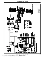
Page 39: ...37 HB Series Desiccant Dryer Models 150 8000 ingersollrandproducts com 14 0 WIRING DIAGRAM WIRING DIAGRAM HB800 HB1800 TM 580095 C 120 26 Dryer Operation Installation Maintenance Manual and Parts ...

Page 40: ...I2 34 0 5 A 0 5 A 2 A 30 1051 1051 8 7 1122 EXPANSION ADAPTER LEFT TOWER DEPRESSURIZATION VALVE REPRESSURIZATION VALVE 1 EXPANSION MODULE 127 126 125 123 124 122 POWER V CABLE 0V 121 120 CABLE P 0V N OV V 1271 1251 AO0 O0 O1 A01 O2 O3 EM 1241 1051 BLOWER STR 1002 15 14 1051 I1 I0 I2 13 I5 I4 I6 I7 EA CABLE 1261 16 RIGHT TOWER DEPRESSURIZATION VALVE 1051 18 1241 1251 1261 1241 1251 1261 34 SSR 2 10...

Page 41: ... O3 EM 1241 1051 BLOWER STR 1002 15 14 1051 I1 I0 I2 13 I5 I4 I6 I7 EA CABLE 1261 16 RIGHT TOWER DEPRESSURIZATION VALVE 1051 18 1241 1251 1261 1241 1251 1261 HEATER SOLID STATE RELAY 2 HEATER SOLID STATE RELAY 1 1002 1051 1122 1122 GND DP 5 1042 1051 1051 1042 1051 1001 22 1 2 3 4 5 6 7 8 9 1 2 3 22 12 11 9 37 7 10 13 30 58 59 60 DISPLAY PANEL 1151 1151 BLOWER AUXILIARY CONTACT STR1 1 DP R1 R1 10K...

Page 42: ...SSR 5 1051 4 SSR 1051 HEATER SOLID STATE RELAY 5 HEATER SOLID STATE RELAY 4 1155 1002 1051 1042 1051 1051 1042 1051 1001 1153 22 FV 4B FV 4D FV 4A FV 4C FV 4E FV 4F FV 4G 1041 5V 0V 5V GND 1042 24V DCPS 24V 5V POWER SUPPLY L N 21 GROUND F6 1L1 F5 1L2 1L3 F7 MOTOR STARTER STR1 MOTOR 1M1 1M2 1M3 MOTOR BLOWER 6T3 6T2 6T1 CONTACTOR CTR2 L1 SSR4 SOLID STATE RELAYS L2 SSR5 SSR3 SSR6 L3 TAN HEATER TAN TA...

Page 43: ...R T 1 SP 1282 1271 1241 1261 1251 1181 1191 1171 1051 1151 1152 1122 1051 GND 1002 1001 1001 1161 10 BLK 3 1 3 1 32 33 35 34 31 30 29 2 WHT 1 26 25 28 27 21 23 24 22 R1 R2 DCPS 24V 1042 DC I2 DC I1 DC I0 DCPS 5V 1041 DCPS 0V 1051 DC AN0 18 19 20 TB 2 SP 1282 1271 14 16 15 17 11 12 13 1241 1261 1251 1181 1191 1171 6 8 9 7 4 5 3 1051 1151 1152 1122 DCPS 0V 1051 1002 GND TB 1 2 1 1001 1001 1152 1152 ...

Page 44: ...42 HB Series Desiccant Dryer Models 150 8000 ingersollrandproducts com 15 0 FLOW DIAGRAM FLOW DIAGRAM HB150 HB400 580477 B 120 26 Dryer Operation Installation Maintenance Manual and Parts ...

Page 45: ...43 HB Series Desiccant Dryer Models 150 8000 ingersollrandproducts com 15 0 FLOW DIAGRAM FLOW DIAGRAM HB500 HB800 580309 C 120 26 Dryer Operation Installation Maintenance Manual and Parts ...

Page 46: ...44 HB Series Desiccant Dryer Models 150 8000 ingersollrandproducts com 15 0 FLOW DIAGRAM FLOW DIAGRAM HB1000 HB1200 580043 D 120 26 Dryer Operation Installation Maintenance Manual and Parts ...

Page 47: ...45 HB Series Desiccant Dryer Models 150 8000 ingersollrandproducts com 15 0 FLOW DIAGRAM FLOW DIAGRAM HB1500 HB8000 580051 E 120 26 Dryer Operation Installation Maintenance Manual and Parts ...

Page 48: ... 631853 631853 631853 2 GAUGE PRESSURE PURGE 0 300 PSI 634278 634278 634278 634278 634278 634278 1 GAUGE PRESSURE TOWER 0 300 PSI 631789 631789 631789 631789 631789 631789 2 GAUGE TOWER TEMPERATURE 631787 631787 631787 631787 631787 631787 2 HEATER 632560 632037 632356 632356 633692 632044 1 MODULE CONTROLLER EXPANSION 633602 633602 633602 633602 633602 633602 1 1 1 1 MODULE CONTROLLER EXPANSION A...

Page 49: ... 300 PSI 634278 634278 634278 634278 634278 634278 1 GAUGE PRESSURE TOWER 0 300 PSI 631789 631789 631789 631789 631789 631789 2 GAUGE TOWER TEMPERATURE 631787 631787 631787 631787 631787 631787 2 HEATER 632044 633792 633725 633725 633741 633741 1 MODULE CONTROLLER EXPANSION 633602 633602 633602 633602 633602 633602 1 1 1 1 MODULE CONTROLLER EXPANSION ADAPTER 683953 683953 683953 683953 683953 6839...

Page 50: ...ONTROL AIR 630524 630524 630524 630524 630524 630524 1 1 1 1 MUFFLER PURGE 680455 680455 633766 633766 633766 633766 OVERLAY CONTROLLER 634088 634088 634088 634088 634088 634088 1 OVERLOAD MOTOR STARTER 633726 683880 683880 683880 684022 684022 1 POWER SUPPLY 5V 24V DC 633665 SP 633665 SP 633665 SP 633665 SP 633665 SP 633665 SP 1 1 1 1 PROBE TEMPERATURE 633609 633609 633609 633609 633609 633609 1 ...

Page 51: ...r HP MCA MOP Width in cm Depth in w o Bypass cm Depth in w Bypass cm Height in cm Air In out Connection Shipping Weight lbs kg Desiccant Weight lbs kg HB150 150 3 1 6 8 45 144 33 84 39 99 66 168 1 1050 476 236 107 HB200 200 4 5 1 7 8 49 124 37 94 45 114 67 170 1 1 2 1150 522 344 156 HB250 250 6 1 5 11 12 53 135 38 97 46 117 68 173 1 1 2 1400 635 398 181 HB300 300 6 1 5 11 12 53 135 38 97 46 117 68...

Reviews: