background image

Lane/5000


900021971 R11 000 05/0917


Copyright© 2017 Ingenico 

All rights reserved


21


Your contactless reader provides four contactless status lights located 

above the contactless logo.


When a contactless transaction is  started 

the  first  (left hand) status light will  be  lit 

steadily; this indicates that the contactless 

is in use but a card is not being read.


When a contactless  card  is  presented  

to the contactless active zone during a


transaction the second, third and fourth 

status lights will  be  lit  in turn. The  card 

read is successful when all four status lights 

are  lit  and a confirmation tone can be 

heard.


CAUTION


Contactless 

status lights


Do not stick any label onto the contactless active zone. It 

can decrease contactless efficiency.


CAUTION


Avoid metallic parts around the contactless area.


5_2 

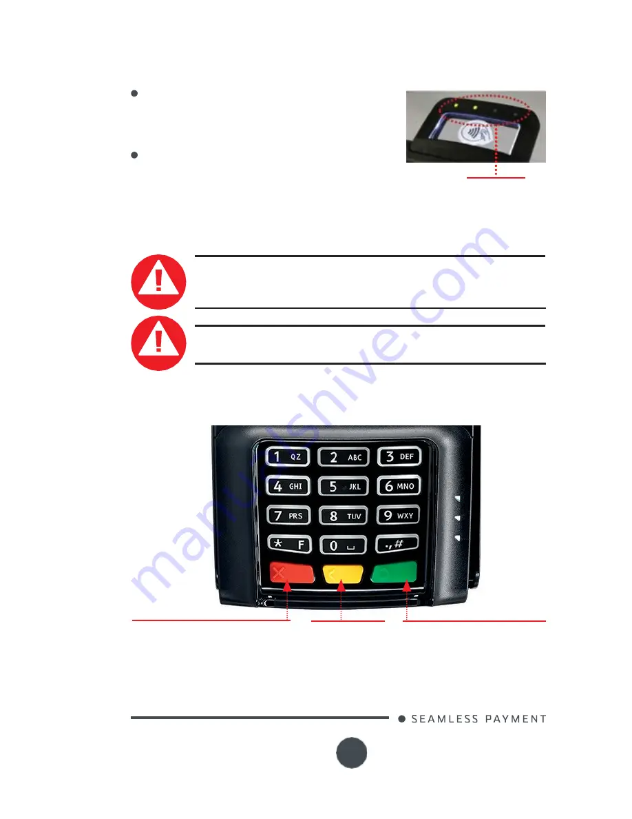
Keyboard details and 

functionality


The red key cancels the procedure


in progress


The yellow key


cancels the last 
character


The green key validates input


selections and information.


It is also used to switch on the 
terminal


Summary of Contents for Lane/5000

Page 1: ...Lane 5000 User Guide www ingenico com 28 32 boulevard de Grenelle 75015 Paris France T 33 0 1 58 01 80 00 F 33 0 1 58 01 91 35 Ingenico SA au capital de 47 656 332 317 218 758 RCS Nanterre...

Page 2: ...empt detection 3_3 Main Characteristics 3_3_1Terminal 3_3_2 Powercharacteristics 4_Installation 4_1 Positioning the terminal 4_2 Connections 4_3 Installing the Terminal 4_3_1 Installing SAM Secure acc...

Page 3: ...d functionality 5_3 Signature capture optional 5_4 Audio jack optional 6_Maintenance 6_1 Cleaning of the terminal 6_2 Transportand storage 6_3 Troubleshooting 6_4 Environment WEE Batteries and Packagi...

Page 4: ...fety precautions unpacking installation and maintenance of your terminal WARRANTY SECURITY To benefit from the guarantee related product and to respect the security we ask you to use only the Ingenico...

Page 5: ...lso include the following items depending on your working configuration Cable specific to your connectivity requirements Power supply unit and power cord A stylus and its holder Screws to fix the main...

Page 6: ...or the power provided by a cash register limited power source LPS Authorized power supply units Power Supply Unit Supplier Type Supplier reference Electrical characteristics Ingenico part number PHIH...

Page 7: ...Must meet standards and regulations in the country of use For type A plug the protection of the installation must be set to 20 A Explosion areas Certain regulations restrict the use of radio equipment...

Page 8: ...being trustworthy The terminal must never be put in or left at a location where it could be stolen or replaced by another device Warranty label under the trapdoor WARNING If the warranty label is torn...

Page 9: ...1 compliant Display Color 3 5 backlit LCD HVGA 480 x 320 pixels Touchscreen Resistive Capacitive Finger stylus 300klifespan signature Finger stylus 1000k lifes pan signature Option Keypad 15 keys rai...

Page 10: ...unit See the list of the authorized power supply units in 3_1 page 6 By POE Power over Ethernet By USB 5VDC or 12VDC POE Power over Ethernet The power sourcing equipment must be compliant with IEEE80...

Page 11: ...reserved 11 3_3_3 Terminal Connectivity USB High speed USB Device in the single connector Ethernet 10 100 Base T Ethernet is available on the Lane 5000 It is recommanded to use TCP Protocol RS232 It i...

Page 12: ...ne 5000 device must be at least 30 centimeters 12 inches away from an electronically active type of security tag deactivation pad An electronically active system sends out a powerful and potentially d...

Page 13: ...Here are all the connections on the terminal The SAMs and the Micro SD A type USB port Optional Multipoint connector Power Supply and communications SD Optional SAM1 Optional according to the model SA...

Page 14: ...by disconnecting the cable Perform the following operations Open the trapdoor Unclip the trapdoor by pushing down on the clip with your finger as shown on the figure hereafter Then lift the trapdoor t...

Page 15: ...talling MicroSD Card optional CAUTION Before starting switch off the terminal by disconnecting the cable Perform the following operations Open the trapdoor Unclip the trapdoor by pushing down on the c...

Page 16: ...ush it to the right until it clicks shut Close down side trapdoor Put the trapdoor onto the bottom casing and then push it upward to clip it 4_3_3 Connecting the terminal to the host CAUTION Connectin...

Page 17: ...can be connected to the host by several ways with optional cables High speed USB device Ethernet RS232 Most of the cables used with iSC and iPP ranges are compatible with the Lane 5000 We advise to c...

Page 18: ...2 cable optional References 296114811AB length 2m 296114928AB length5m Power supply unit USB cable optional References 296111170AD length 2m 296114303AD length 4m Power supply unit USB powered 12V cab...

Page 19: ...ed on the left side of the terminal Remove the adhesive protection insert the pin of the holder inside the Kensington hole and press firmly in place A magnet in the holder keeps the stylus in position...

Page 20: ...eader make sure that the magnetic stripe on the card is facing the Lane 5000 display screen see Swiping a Magnetic Stripe Card Swipe the card with constant speed neither too slowly nor too fast to max...

Page 21: ...active zone during a transaction the second third and fourth status lights will be lit in turn The card read is successful when all four status lights are lit and a confirmation tone can be heard CAUT...

Page 22: ...stylus type resistive or capacitive is used with the corresponding touchscreen type as a resistive stylus is not working with a capacitive screen 5_4 Audio jack optional The audio jack is located next...

Page 23: ...s cleaners that contain chemicals too harsh for these sensitive screens plasma television screens LCD and LED monitors touch screen monitors and POS screens all fall under this category Ingenico dual...

Page 24: ...see Swiping a Magnetic Stripe Card section 5 1 1 Make sure that the Lane 5000 connector is fully inserted into the back of the device Restart the device If you have another working Lane 5000 device s...

Page 25: ...sly approved by the party responsible for compliance could void the user s authority to operate the equipment 6_4 Environment WEEE Batteries and Packaging This product is labelled in accordance with E...

Page 26: ...h the instructions may cause harmful interference to radio communications However there is no guarantee that interference will not occur in a particular installation If this equipment does cause harmf...

Page 27: ...na of a type and maximum or lesser gain approved for the transmitter by Industry Canada To reduce potential radio interference to other users the antenna type and its gain should be so chosen that the...

Page 28: ...that have been designed in a way so as not to require a safety connection to electrical earth These products must NOT have a safety connection to Earth This logo indicates that the product operates wi...

Page 29: ...any other recipient of this document or information contained therein is held responsible to INGENICO for the confidentiality of that information Care has been taken to ensure that the content of this...

Reviews: