11
Release 07/22
Roadside Safety Barrier
Figure 10: Z-Post on Base Plate
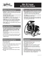
7.6 Post Pullover Test
In the event that the soil type cannot be verified, the
suitability of the post foundation can be established
through a post pullover test.
This is undertaken by applying a 1kN load to the post,
550mm above ground level. The load is applied prior to
the attachment of the rail. Displacement at the base of
the post shall not exceed 1mm whilst the load is applied.
An alternative post pull over test can be achieved via a
more destructive means, whereby a load of 1.2 tonnes is
applied to the test post at a height of 700mm. This loading
approximates the probable capacity of the post and
should be able to be maintained with minimal rotation
of the post in the soil. At the completion of the testing
the post should be removed from the test location and
should not be used in the installation.
7.7 Posts on Base Plates
In the event that the Z-post cannot be installed to
the required in-ground depth, the use of a base plate
mounted on a suitable foundation can be adopted. Posts
on base plates are typically used at culvert locations, and
in areas where underground services restrict posts from
being driven into the ground. Refer to Ingal Civil Products
drawings for the installation of posts on base plates.
7.8 Z-Posts in Rock
Traditional guardrail posts are designed to yield in the
surrounding soil and their placement in rock or concrete
is problematic. Restraining the traditional posts by setting
them in narrow holes drilled into rock, setting them in
concrete or placing a mowing strip around the posts
can lead to a failure of the system to safely contain and
redirect the errant vehicle.
The specially engineered Z-post dissipates energy by
yielding through bending near ground level. This means
that typical recommendations for the installation of a
traditional guardrail post in rock are not applicable to
the Z-post. When rock is encountered, the installation
guidelines as detailed in Table 4 are applied. If required
the bottom of the post may be cut onsite by a disc
grinder or equivalent steel cutting tool. A corrosion
resistant treatment will need to be applied to the freshly
cut surface, ICP recommend a Zinc metal spray in
accordance with ISO 2063 or AS/NZS 2312.
7.9 Non-Standard Post Spacing
Occasionally, a roadside hazard may prevent a post from
being installed at the recommended spacing. In these
instances it may be possible to stiffen the barrier with
reduced post spacing on the approach and trailing side
of the hazard, we would recommend you discuss these
options with your local Ingal Civil Products representative.
7.10 Delineation
A specially designed delineator is attached to the Z-post.
Typically, delineation is arranged so that drivers approaching
from either direction will see only;
•
Red retro-reflectors on their left;
•
White retro-reflectors on their right
on two-way carriageways; and
•
Yellow retro-reflectors on their
right on one-way carriageways
and medians separating traffic in
opposing directions
The spacing of delineators is
dependant upon driver line of sight. As
a general rule delineators are provided
for installation every 20m on straight
alignments. Installation on curves will
require a closer spacing dependant
upon the radius of the roadway.
Figure 9: Z-Post Pullover Test
1kN Force
700mm
Embedded Z-Post
Ground Level
Displacement
less than 1mm
1kN Force
550
mm
Embedded Z-Post
Ground Level
Displacement
less than 1mm
Summary of Contents for Ezy-Guard Smart
Page 1: ...www ezyguard com Release 07 22 ProductManual ...
Page 21: ...21 Release 07 22 20 Release 10 14 ...
Page 22: ...22 Release 07 22 ...
Page 23: ...23 Release 07 22 22 Release 10 14 ...
Page 24: ...24 Release 07 22 ...
Page 26: ...26 Release 07 22 ...
Page 27: ...27 Release 07 22 ...
Page 28: ...28 Release 07 22 ...
Page 29: ...29 Release 07 22 ...
Page 30: ...30 Release 07 22 Notes ...
Page 31: ...31 Release 07 22 Notes ...