


6.
OPERATING THE SPECTRAL MULTIMETER USING
THE COMPUTER INTERFACE
6.1. INTRODUCTION
The Spectral Multimeter can be operated from a host by sending commands to it through a
computer interface on the rear panel.
Section 6 describes how to set up, configure, and operate the Spectral Multimeter via the RS-232
or the IEEE-488 interface.
With the IEEE-488 interface the instrument is fully programmable for use on the IEEE standard
488.1 interface bus and also complies with the supplemental standard 488.2.
6-1
6-2
7
6.2.
LOCAL AND REMOTE OPERATIONS
When the Spectral Multimeter is operated from a host then it is operated „remotely“, when
operated from its front panel the Spectral Multimeter is operated „locally“.
The Spectral Multimeter is no longer controllable from the front panel when via interface the
Local Lockout
state has been enabled.
6.3. COMPUTER
INTERFACES
Your Spectral Multimeter can be equipped without interface, with RS-232 interface (Option 01),
or with both RS-232 and IEEE-488 interface.
You can check in the
SETUP
menu which options you have installed. If an interface is not
installed its parameters are marked n/a (not available).
Basically, you can operate both, the RS-232 and the IEEE-488 interface, simultaneously. Due to
limited rear panel space you may have difficulties installing both interface connectors.
6.4.
SETTING INTERFACE PARAMETERS
The Spectral Multimeter sets the parameters at startup to the following default values:
Band:
9600
Parity:
None
Terminator:
CR
Handshake:
None
IEEE-address: 1
Above parameters can be changed by entering the
SETUP
menu via the front panel or by sending
commands through the computer interface. Interface settings can be stored in none-volatile
memory and are selected at start-up if the recall number is selected accordingly (section 5.14.). In
order for the Spectral Multimeter and the host to communicate through the interface the
communication parameters of the Spectral Multimeter must match those of the host.
6.5.
CABLING THE SPECTRAL MULTIMETER TO A HOST
Turn Spectral Multimeter off. When cabling is complete turn power on again.
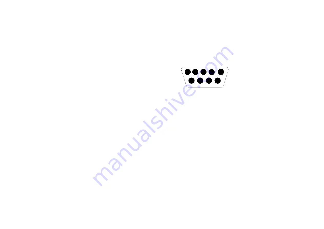
The RS-232 interface on the Spectral Multimeter rear panel uses a DB-9 connector. Its pinout is
given below.
1
DCD
Data Carrier Detect
2 RxD Received
Data
3 TxD Transmitted
Data
4
DTR
Data Terminal Ready
5 Grd
Signal
Ground
6
DSR
Data Set Ready
RTS
Request to Send
8
CTS
Clear To Send
9 RNG Ring
1
5
9
6
Use a one-to-one connected (TxD and RxD not crossed) RS-232 cable. Its length should be less
than 15m to make sure not to exceed the allowable (2000pF) cable capacitance.
To use the IEEE-488 interface cable the Spectral Multimeter to a host.
The IEEE-488 operation is governed by following limitations: a maximum of 15 devices can be
connected in a single bus system; the maximum length of cable must be less than 20m or 2m times
the number of devices in the system.
6.6.
HOW THE SPECTRAL MULTIMETER PROCESSES
INPUT
The Spectral Multimeter processes and executes valid input strings sent by the host. The input
string is followed by an input terminator such as
CR/LF
(carriage return/line feed).
When the Spectral Multimeter receives input, it stores it in a 32 byte input buffer. As soon as the
input terminators have been recognized the data in the buffer are processed.
The Spectral Multimeter accepts upper and lower case characters. If a command can not be
understood, or it was longer than 32 characters which can not be the case for correct commands,
the command will be ignored and an error will be generated.
For the RS-232 you can select the Xon hand shake modus. Xon signals the host to stop
transmission when the input buffer of the Spectral Multimeter is full. If in this process information
gets lost a device dependent error will be generated.
Summary of Contents for SM201
Page 28: ......