


26
XtrapulsEasy
™-DB - Installation Guide
Chapter 5 - Appendix
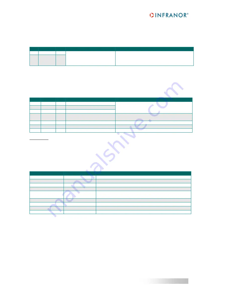
5.1.2.3 - X3 connector: +24 V
Manufacturer: Wago
Type: Midi connector
Reference: 721-102/026-000
PIN
SIGNAL
I/O
FUNCTION
DESCRIPTION
1
24V
I
Mains isolated 24V
DC
auxiliary
power supply
0V input referenced to the GND
potential on the drive housing
24V
DC
supply: +/- 15%
Consumption: 300mA without digital output loads
2
0V = GND
I
5.1.2.4 - X4 connector: Motor phases and power supply
Manufacturer: Phoenix Contact
Type: PC 5/ 7-STCL1-7.62
Reference: 1778117
Tightening torque: 0.7 to 0.8Nm
PIN
SIGNAL
I/O
FUNCTION
DESCRIPTION
1
U
O
Motor phase U
Shielded motor cable with 360° shield connection.
2
V
O
Motor phase V
3
W
O
Motor phase W
4
GND
I/O
GND reference and PE
connection
Connect GND signal of the chassis and PE cable of
the motor to this pin.
5
DC-
I/O
DC bus negative voltage
6
DC+
I/O
DC bus positive voltage
7
NC
-
Not used
IMPORTANT
Motor cables must be shielded.
The 360° shield connection must be ensured by metallic collars and connected to the ground reference potential.
The GND wire of the motor cable MUST be connected to pin 4 of the X4 connector.
See section 4.1.4 for grounding and shielding precautions.
5.1.2.5 - X5 connector: CAN & RS232
SUB D 9 pin male connector
PIN
FUNCTION
REMARKS
1
Termination resistor Connect X5.1 to X5.7 to enable the termination resistor
2
CAN-L
Line CAN-L (dominant low)
3
GND
GND signal for CAN communication
4
TXD
Transmit data RS-232
5
GND
GND (shield connection if no 360° connection on the connector).
360° shield connection is highly recommended.
6
Reserved
7
CAN-H
Line CAN-H (dominant high)
8
RXD
Receive data RS-232
9
Reserved
Default parameters for the CANopen® bus are:
-
Transmission speed of 1Mb/s,
-
Address set at 1,
Please see
Gem Drive Studio Software Quick Start manual
for detailed information on changing this
configuration.


