


20
Chapter 4 - Connections
XtrapulsEasy
™-DB - Installation Guide
4.3 - ACCESSORIES AND CONNECTIONS
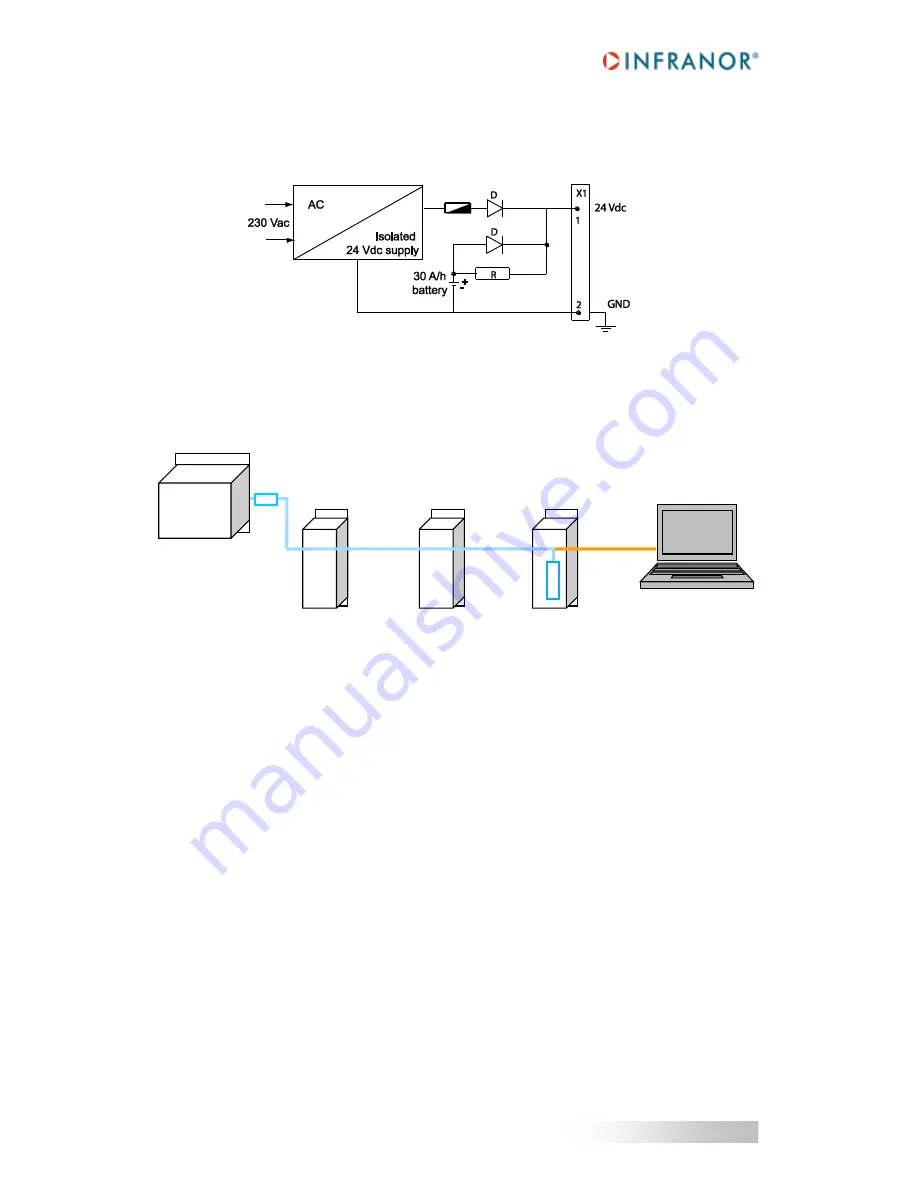
4.3.1 - Connection of a backup battery
The Xtrapuls
Easy™ drive consumption is less than 100mA with 24V
DC
. So, a 24V / 30A/h battery can keep the
drive powered during approx. 10 days. This backup method is interesting for saving the machine initialization as
well as the axis position even when moving with the mains switched off.
4.3.2 - Multi-axis connection of the serial link
The parameterization of all axes is made by one single connection to the first axis via the serial link RS232. The
other axis are parameterized via the CAN bus.
4.4 - WIRING INSTRUCTIONS
According to the EN61000.4-2-3-4-5 and EN55011 standards.
4.4.1 - Motor, resolver and encoder cables
Motors, resolvers and encoders are grounded via their housing.
Cable inputs must be made by means of metal connectors with collars allowing the 360° shield connection.
The resolver cable must be pair twisted and shielded (sin, cos, ref.). Motor cables MUST also be shielded and
connected over 360° at both ends.
Encoder inputs A, B, C, D, Z and R require pair twisted and shielded cables. The shield must have a 360°
connection via metallic collars at both ends.
RS 232
Setup
monitoring
Host controller
CANopen® DS402
CAN bus
CAN bus
RT
R
T
RT = 120
Ω
terminal resistor connected between CAN-L and CAN-H lines


