background image

INFOSEC UPS SYSTEM

 - 4, rue de la Rigotière - 44700 Orvault - France - www.infosec.fr 

Hot Line : 

 tél : +33(0)2 40 76 15 82 - 

fax :

 +33 (0)2 40 94 29 51- [email protected] - 10 05 04 205 02 

17

 - 

5 DESCRIPTION 


5.1 Face 

Avant 


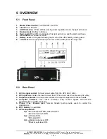
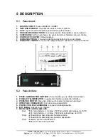
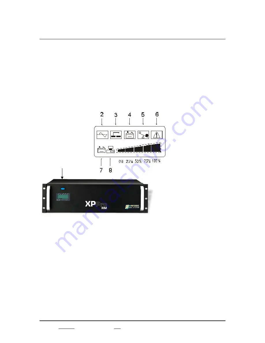
1.   BOUTON ON/OFF:

 bouton MARCHE / ARRET. 

2.   SECTEUR PRESENT:

 Voyant Mode secteur, secteur présent. 

3.   AVR : 

voyant mode AVR éclairé quand l’UPS régule la tension.


4.   ONDULEUR SUR BATTERIE:

 Fonctionnement en Mode batterie, secteur absent. 

5.   SURCHARGE:

 UPS en surcharge, le voyant s’éclaire et l’alarme sonne en continu. 

6.   SORTIE UPS COUPEE:

 Défaut onduleur. 

7.   NIVEAU BATTERIE:

 % niveau de décharge des batteries en mode batterie. 

8.   NIVEAU DE CHARGE: 

% niveau de charge indique la quantité de matériel connecté.


5.2 Face 

Arrière: 


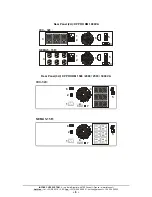
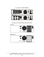
1.  PRISE ALIMENTATION SECTEUR :

 Prise d’entrée pour le câble d’alimentation. 

2. FUSIBLE D’ALIMENTATION :

 Logement du fusible de protection d’entrée. 

3. PRISES DE SORTIE:

 Prises de sortie pour connecter le matériel à protéger. 

4.  INTERFACE ORDINATEUR : 

Port de communication DB9. 

5.  PROTECTION TEL/FAX/MODEM :

 connexion RJ téléphone/fax. 

6. EXT. Battery:

 Absent sur ce modèle. 

7.  MICRO SWITCH REGLAGE UPS:


Dip1. 

…

 En mode batterie : si charge < 50W pas d’arrêt automatique de l’UPS. 


†

 En mode batterie : si charge < 50W arrêt automatique de l’UPS. 

Dip2. 

†

 Possibilité de démarrage sur batteries activée. 

…

 Possibilité de démarrage sur batteries désactivée. 

Dip3. 

†

 Alarme sonore auto-reset OFF. 


…

Alarme sonore auto-reset ON. 


Summary of Contents for XP PRO RM

Page 1: ...USER GUIDE 1 NOTICE D UTILISATION 13 XP PRO UPS 1000 1500 2000 2500 3000VA...

Page 2: ...1 Front Panel 5 5 2 Rear Panel 5 5 3 Position 7 6 INSTALLATION AND OPERATION 8 7 COMPUTER INTERFACE 9 8 BATTERY FACTS 10 9 SPECIFICATIONS 11 10 TROUBLE SHOOTING 12 SOMMAIRE 1 IMPORTANT 13 2 AVERTISSEM...

Page 3: ...installation and operating instructions that will help you derive the fullest performance from the UPS Please save this manual It includes important instructions for the safe and good use of this UPS...

Page 4: ...ith significant inductive loads such as motors fluorescent lamps Be sure to operate within the power rating of the UPS Below 1 2 or 1 3 of rated power is recommended for longer backup time longer batt...

Page 5: ...sion through the modular connectors on the back panel The XP PRO UPS and RUPS 2000 monitoring software make your computer operate intelligent and provide you with the ability of a perfect protection o...

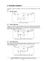
Page 6: ...tput loop and the battery charging loop The AC output gets power from AC utility input and pass through AVR to support power to load In the same time the AC utility input is converted by AC DC CHA and...

Page 7: ...e UPS battery is being used 8 Load Level A bar graph showing how much of the UPS power is being used 5 2 Rear Panel 1 AC line input socket Connect power cable from the UPS to AC utility 2 AC input fus...

Page 8: ...nfosec fr Hot Line t l 33 0 2 40 76 15 82 fax 33 0 2 40 94 29 51 hotline infosec fr 10 05 04 205 02 6 Rear Panel 2U XP PRO RM 1000VA 1 2 1 2 3 3 4 4 5 5 6 6 Rear Panel 3U XP PRO RM 1500 2000 2500 3000...

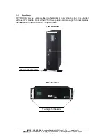
Page 9: ...c fr 10 05 04 205 02 7 5 3 Position XP PRO UPS may be installed either in a horizontal or in a vertical position It is provided with one UPS stand to stabilize the UPS in tower position and two angle...

Page 10: ...f position and insure that the voltage of the AC utility source corresponds to the nameplate on the UPS rear panel 2 Plug the power cable into the grounded socket If indicators of LINE ON CUT OFF LCD...

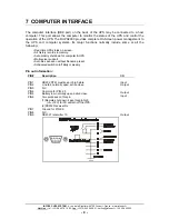
Page 11: ...mally include some or all the following Real time UPS status on screen All history records in memory Auto orderly shutdown for computer UPS Multi server support Auto file save even without filename pr...

Page 12: ...use because it may cause batteries over drain WARNING Only a qualified technician should replace the battery Batteries have high short circuit current capacity mistakes in connecting or disconnecting...

Page 13: ...H 4PCS 12V 9AH 4PCS Battery Recharge Time 5 hours to 90 of full capacity Indicator LCD LCD indicator for line on battery back up AVR protection Overload and cut off Load and battery level Battery Back...

Page 14: ...owing information when call for service to 33 2 40 76 15 82 Model number serial number Date of the problem occurred date of purchase Full description of the problem including load LCD and alarm status...

Page 15: ...allation et de bon fonctionnement de ce mat riel afin de vous offrir un maximum de performance et de long vit Garder de cot ce manuel Il indique les conditions de s curit pour son utilisation ainsi qu...

Page 16: ...nductives telles que les moteurs et les lampes fluorescentes S assurer que la charge prot ger est en dessous de la puissance nominale de l onduleur Une charge de 1 2 ou 1 3 de la puissance nominale es...

Page 17: ...l phonique est situ e l arri re de l appareil Le logiciel RUPS2000 permet la communication avec l UPS contacts secs 3 2 Caract ristiques Design Line interactive Ecran LCD Autor gulation AVR pour comp...

Page 18: ...premier va vers la sortie et le second vers le chargeur batterie La tension d entr e INPUT traverse l AVR et est achemin e vers la sortie OUTPUT pour alimenter la charge Parall lement le circuit AC D...

Page 19: ...s en mode batterie 8 NIVEAU DE CHARGE niveau de charge indique la quantit de mat riel connect 5 2 Face Arri re 1 PRISE ALIMENTATION SECTEUR Prise d entr e pour le c ble d alimentation 2 FUSIBLE D ALIM...

Page 20: ...sec fr Hot Line t l 33 0 2 40 76 15 82 fax 33 0 2 40 94 29 51 hotline infosec fr 10 05 04 205 02 18 Face Arri re 2U XP PRO RM 1000VA 1 2 1 2 3 3 4 4 5 5 6 6 Face Arri re 3U XP PRO RM 1500 2000 2500 30...

Page 21: ...10 05 04 205 02 19 5 3 Positionnement Les onduleurs XP PRO peuvent tre positionn s soit horizontalement soit verticalement Ils sont fournis avec un pied pour la stabilisation en position tour et avec...

Page 22: ...e signal tique l arri re de l appareil 2 Branchez la prise d alimentation une prise secteur Si les voyants SECTEUR PRESENT 2 et SORTIE UPS COUPEE 6 sont allum s le secteur est normal mais l onduleur e...

Page 23: ...nts Fermeture automatique de vos PC et onduleur Sauvegarde automatique des fichiers Une horloge permet d allumer ou d teindre l UPS chaque jour ou chaque semaine Utilisation des broches du connecteur...

Page 24: ...u moins tous les 3 mois pour viter les d charges profondes et leurs d t riorations ATTENTION Seul un technicien est habilit remplacer les batteries Les batteries poss dent un fort courant de court cir...

Page 25: ...emps de recharge 5 heures 90 de sa capacit Ecran LCD Ecrans LCD indiquant pr sence secteur autonomie des batteries backup AVR r gulation de tension surcharge et d fauts cut off les niveaux de charge e...

Page 26: ...num ro de s rie de l onduleur voir plaque signal tique au dos Date d apparition du probl me date d achat de l onduleur Description compl te du probl me mat riel connect tats des voyants du LCD condit...

Page 27: ...mergency Backup Power Supply For Use With Computer Loads Only Intelligent Auto Shutdown Software Power Surge Noise Protection Internet Line Protection Cost Efficiency AVR Protection Compact Reliable D...

Reviews: