background image

INFOSEC UPS SYSTEM – 15 rue du Moulin – 44880 SAUTRON - FRANCE - www.infosec-ups.com 

Hot Line – Tel + 33 (0)2 40 76 15 82 - Fax + 33 (0)2 40 94 29 51 - [email protected] – 11 16 AA 59 203 04 

Do not obstruct the ventilation slots. Install the unit in an environment which is free from 
dust, chemical vapours and conductors. Moreover, in order to avoid any interference, keep 
the UPS at least 20cm away from the CPU (central processing unit) or surrounding walls. 


4.


Connection 

Connection of the UPS to the utility 
First, check the identification plate at the back of the UPS to make sure that the power 
supply is compatible with the network’s voltage and that the device is powerful enough to 
protect the given load.  
Then, plug the UPS to the utility (wall outlet). 
The mains socket outlet that supplies the UPS must  be installed near the UPS and be 
easily accessible. The UPS power cord must be connected to an earthed mains socket 
outlet. 


Connection of the devices to the UPS 
Plug the loads to the output outlets. 
Do not attach a power strip or surge suppressor to the UPS. 


Connection of the Modem/Phone Surge Protection 
Connect a modem or phone line to the surge protected “IN” outlet of the UPS. Connect the 
computer with a phone cable line to the “OUT” outlet of the UPS.


Connection of the USB cable or RS232 cable  
Please note the RS232 port is only available for 2400 VA model. 
Install the InfoPower software (CD included with the UPS) on the computer. 
Connect the USB  or RS232  cable from the computer to the UPS. It is then possible to 
program remote shutdowns/starts of the UPS, and to monitor its events history. 


5. On/Off


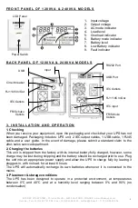
Press the UPS On/Off switch and the UPS comes on in normal run mode.  
Press the UPS On/Off switch to turn it off. 
In the event of an emergency, press the OFF button and disconnect the power cord from 
the AC power supply to disable the UPS properly. 


Note

: 1 - 

For correct use, please turn the UPS on before the PC and other loads, and turn 

it off after the connected loads are turned off. 
2  –  We recommend you leave the UPS on the rest of the time with the battery charging 
(even if the loads are turned off). This will help extend the battery’s useful life.


6. DC Start 

HERO  units are equipped with an integrated DC start function. To start the UPS in the 
absence of a power supply and with a full battery, simply press the button. 


4 .   W A R N I N G S  


Applications for Hero Pro Dual Plug 
Hero Pro Dual Plug must not be used to supply load to the following appliances. Such use 
could damage the UPS: 

  a laser printer 

  a scanner 

  medical equipment 

  vacuum cleaners 

Do not plug the UPS into its own output. 


5 .   B A T T E R Y  


The battery is the only UPS component which is not in permanent use. It has a useful life 
of approximately 3 to 5 years. However, frequent major discharges or exposure to 
temperatures over 20

°

C will shorten its life span. We therefore recommend that users 

recharge the battery once every 3 months when the unit is not in use in order to 

Summary of Contents for HERO PRO DUAL PLUG 1200

Page 1: ...700 VA 1200 VA 2400 VA User guide____________________________________ 2 Manuel d utilisateur____________________________ 9...

Page 2: ...t or near heater o Do not block air vents in the housing of UPS The UPS must be installed in a location with good ventilation Ensure enough space on each side for ventilation o The mains outlet that s...

Page 3: ...ors or fluorescent lights o Do not connect any household appliances such as microwaves vacuum cleaners hair dryers or life support systems to the UPS o Due to excessive consumption laser printers shou...

Page 4: ...equipment category At the end of its useful life it must be disposed of separately and in an appropriate manner This symbol is also affixed to the batteries supplied with this device which means they...

Page 5: ...s internal battery fully charged however some charge may be lost during shipping and the battery should be recharged prior to use Plug the unit into an appropriate power supply and allow the UPS to ch...

Page 6: ...nfoPower software CD included with the UPS on the computer Connect the USB or RS232 cable from the computer to the UPS It is then possible to program remote shutdowns starts of the UPS and to monitor...

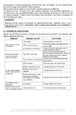
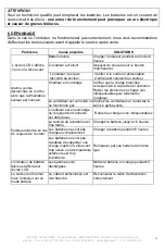
Page 7: ...ectly we recommend you perform the following tests before calling the Hot Line PROBLEM POSSIBLE CAUSE SOLUTIONS LCD screen is off on front panel Low battery Charge battery for 6 hours UPS is not turne...

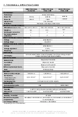
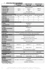
Page 8: ...oltage 220 230 240 V Voltage regulation 10 Frequency 50 or 60 Hz 1 Hz INDICATORS LCD Display AC mode Battery Mode Load Level Battery Level Input Voltage Output Voltage Overload Fault and Low Battery A...

Page 9: ...s d un appareil de chauffage o Ne pas obturer les grilles de ventilation de l onduleur Il doit tre install dans un local bien ventil Laisser suffisamment d espace de chaque c t pour l a ration o La p...

Page 10: ...S assurer que la charge aliment e n est pas sup rieure la capacit de l onduleur Afin d obtenir une dur e de secours plus importante et une plus longue dur e de vie des batteries nous recommandons de l...

Page 11: ...ns suivantes doivent tre prises par le technicien qualifi Ne pas porter de bagues montres et autres objets m talliques Utilisez des outils avec manche isol D connecter l alimentation et les prises de...

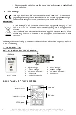
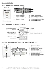
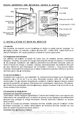
Page 12: ...on en sortie 3 Indicateur mode secteur 4 Niveau de charge 5 Niveau de surcharge 6 Indicateur mode batterie 7 Niveau de batterie 8 Indicateur de batterie faible 9 Indicateur de d faut Prise de courant...

Page 13: ...selon charge connect e 3 Lieu et installation L onduleur est con u pour une installation en environnement prot g une temp rature comprise entre 0 C et 40 C et un taux d humidit compris entre 0 et 90 s...

Page 14: ...es puis teignez le apr s que les charges connect es soient teintes 2 Nous vous recommandons de laisser l onduleur le reste du temps avec la batterie charg e m me si les charges sont teintes Cela aider...

Page 15: ...alors que l alimentation secteur est normale Onduleur en surcharge V rifier que la charge branch e correspond la capacit de l onduleur Retirer les l ments en charge non indispensables puis red marrer...

Page 16: ...nce 50 or 60 Hz 1 Hz INDICATEURS cran LCD Mode secteur mode batterie niveau de charge en sortie niveau de la batterie tension d entr e tension de sortie surcharge d faut et batterie faible INDICATEURS...

Reviews: