6
1.2.2 The Power Configuration of UPS
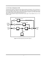
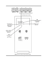
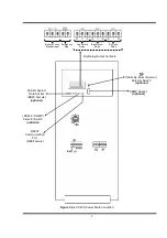
The power switch location of the ML-300 series UPS’s are shown in the figures 1.1-2-3-4 In the figure 1.2
external (split) by-pass block diagram is given. Optionally the static and mechanic by-pass line can be
connect to a different 3 phase AC source ( other UPS etc.),and the rectifier input is connected to generator or
mains voltage. If there is no other power supply static and mechanic by-pass line input (S2) and the rectifier
input connections will be connect to each other. (See figure 1.1)
During the normal operation except the maintenance by-pass switch, all the Switches will be at “1-On”
position (closed).
3 phase
load
output
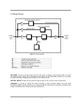
Inverter
Rectifier
Static By-Pass
Static Transfer Switch
Maintenance Bypass
Mechanic transfer switch
3 Phase
Line
Input
Battery group
S3
S2
S1
S5
S4
3 Phase
By-Pass
Supply
Input
Figure 1.2 UPS Split (external) By-Pass Block Diagram
Summary of Contents for MagicLight ML-310
Page 2: ......
Page 27: ...24 Figure 3 2 Parallel UPS connection...
Page 36: ...33 optional Figure 5 3 b UPS Battery Group Connection With Battery Fuse...
Page 43: ...AGKK9241 05 2013...

