


3x1 Wallplate Transmitter Switcher Kit
INFOBIT AV
www.infobitav.com
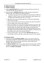
3)
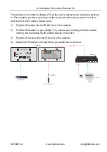
If the switcher needs to be controlled by receiver end, the control device (e.g. PC)
can be connected to the RS232 port of the receiver, the connection diagram shown
as below:
7.2
RS232 Commands
After set all needed input and output devices according to the RS232 connection
diagram, please install the RS232 control software (e.g. docklight) into the control PC to
send RS232 command.
After installing the RS232 control software, please set the parameters of COM number,
bound rate, data bit, stop bit and the parity bit correctly, and then you are able to send
command in command sending area.
When controlling the switcher, the serial port settings for all RS232 commands is:
Baud rate: 9600
Data bit: 8
Stop bit: 1
Parity bit: none
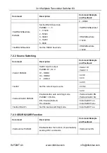
7.2.1
Device Control
Command
Description
Command Example
and Feedback
>GetFirewareVersion
Get firmware version.
<V1.0.0
>SetFactoryReset
Restore factory default.
<FactoryReset_True
>SetReboot
System reboot.
<Reboot_EN
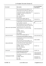
>SetHelp PARAM
Get the command function and usage.
>SetHelp SetAV
<Switch an input AV
signal to outputs
>SetAV Param
Param = H1, H2, C
H1 - HDMI1
H2 - HDMI2
Tx
Rx
1
2
3
HDCP
LINK
HDBT OUT
PoC
Receiver
PC
Transmitter
PoC


