


3x1 Wallplate Transmitter Switcher Kit
INFOBIT AV
www.infobitav.com
Command
Description
Command Example
and Feedback
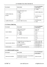
>SetOffMsgLoopCnt
PARAM
Set the number of times to send the
DISPLAY OFF RS232 command.
PARAM=1 ~ 2
>SetOffMsgLoopCnt 1
<OffMsgLoopCnt 1
>GetOffMsgLoopCnt
Set the number of times to send the
DISPLAY OFF RS232 command.
>GetOffMsgLoopCnt
<OffMsgLoopCnt 1
>SetOffMsgLoopDelayTime
PARAM
Set the sending interval between two
Display OFF RS232 commands.
PARAM=5 ~ 100 (1=100ms)
>SetOffMsgLoopDela
yTime 5
<OffMsgLoopDelayTi
me 5
>GetOffMsgLoopDelayTime
Get the sending interval between two
Display OFF RS232 commands.
<OffMsgLoopDelayTi
me 5
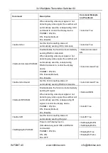
>SetPanelCEC PARAM
Set the delay time of sending DISPLAY
OFF CEC command. When no signal input,
the display device will be automatically
turned off when the delay time is up.
PARAM = 0 ~ 1800 (second)
>SetPanelCEC 600
<PanelCEC 600
>GetPanelCEC
Get the delay time of sending CEC
command of turning off display device.
<PanelCEC 600
7.2.4
EDID Management
The Extended Display Identification Data (EDID) is used by the source device to match
its video resolution with the connected display. By default, the source device obtains its
EDID from the connected display, but if EDID communication is failed, 4K@30Hz 8bit
Stereo Audio will be used as default output resolution.
In addition, since USB-C input only supports 4K@30Hz, so some limitations have been
done on USB-C input. If the video resolution of display is lower than 4K@30Hz
(including 4K@30Hz), the source device will copy and output it. But if the video
resolution of display is higher than 4K@30Hz, the video resolution of source device will
be fixed at 4K@30Hz.
Meanwhile, since the display with different capabilities is connected to the switcher, the
below RS232 commands can be used to set the EDID to a fixed value to ensure the
compatibility in video resolution.
Command
Description
Command Example
and Feedback
>SetInPortEdid PARAM
Set EDID.
PARAM = 0 ~ 9
>SetInPortEdid 0
<InPortEdid 0


