InfluxGreen Energy Pte Ltd
Model:
IGSI-3 Phase Output Ser ies
Rev. 0
17
3. OPERATION METHOD
3 . 1 C o n t r o l P a n e l
There is a LCD screen, three LEDs and four function keys on the front panel of the solar
inverter. The LCD and LED provide the status of your Inverter. You also can use the function
key as a simple control for scrolling and viewing data.
Fig. 12 Control panel
A. LCD Screen: Display the operating data and conditions, warning/error codes and
relevant inverter information.
B. The model of inverter (for example,IGSI-1000SJ)
C. ALARM LED: Indicates the alarm of the inverter.
D. POWER LED: Indicates the inverter is running normally.
E. Fault LED: Indicates the fault of the inverter.
F. Function Key: Shall be used to set different parameters and display language for the
inverter.
G. Description of inverter
Note:
To save power, the LCD display’s backlight automatically turns off after 10 seconds.
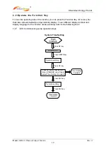
There are 4 buttons on the panel’s function keys: UP, DOWN, ESC ,OK
UP button: Move cursor to up or increase the values
DOWN button: Move cursor to down or decrease the values.
ESC button: Exit current screen or selection
OK button: Confirm the selection.
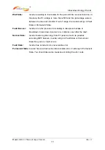
LED indicators
Information List
Green LED
Yellow LED
Red LED
Wait State
FLASH
OFF
OFF
Fault Revover
OFF
ON
OFF
Normal State
ON
OFF
OFF
Fault State
OFF
OFF
ON
Permanent State
ON
OFF
OFF


