Inflight Fitness MULTI-FLY/DELT Assembly Manual Download Page 3

0B

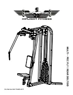
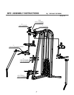
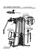
MFD ASSEMBLY INSTRUCTIONS 


1B

IMPORTANT NOTICES 


Read all warning labels, the instruction placard and this manual before 
attempting to use this machine.  Always consult your physician and an 
exercise professional before beginning any exercise program/regimen. 
 
Before any test or use check for proper assembly of the machine including 
(but not limited to): bolts and other hardware fastened properly, cables in 
pulley grooves and routed correctly. For safety use the top weight only for 
the first machine movement.  
 
Maintain your machine in good working order by following the maintenance 
schedule provided on the equipment.    

 
It is strongly recommended that a qualified dealer assemble this 
MULTI-FLY/DELT machine 
 
Should there be any question during assembly contact your authorized Inflight 
Fitness dealer or call direct to 714 821 4177. 
 
Before beginning assembly read this instruction manual thoroughly.  Unpack and 
verify all parts and hardware quantities against the parts and hardware lists. 
 
Follow the assembly steps in sequence.  Failure to follow the order of assembly 
will result in disassembly later and possible damage to the machine components. 
 
The 3/8” nuts provided with this machine are “centerlocking”.  They provide a 
more secure assembly than nylon locking nuts.  Please note they do require 
more force to tighten than nylon locking nuts. 


Summary of Contents for MULTI-FLY/DELT

Page 1: ......

Page 2: ......

Page 3: ...maintenance schedule provided on the equipment It is strongly recommended that a qualified dealer assemble this MULTI FLY DELT machine Should there be any question during assembly contact your authori...

Page 4: ...TY Bolts 3 8 x 8 4 3 8 x 5 6 3 8 x 3 2 3 8 x 2 4 3 8 x 2 1 3 8 x 1 2 3 8 x 1 4 x 3 4 x 1 2 6BScrews 3 8 x Buttonhead Screws 4 7BWashers and Nuts 3 8 Curved Washers 4 3 8 Flat Washers 40 3 8 Nuts Cente...

Page 5: ...rm Seat Support Back Support R H Arm Plate 2 hole 8BBLACK FRAME PARTS L H Cam R H Cam 9BCABLES AND PULLEYS MFD Cable 4 Pulleys 3 10BMISCELLANEOUS Guide Rods 2 Lube Weight Stack Cushions 2 Seat Pad Bac...

Page 6: ...s into the base of the Loop Upright Allow Guide Rods to lean back towards stabilizer Place one weight stack cushion on each Guide Rod and slide down to the base Apply lubricant to the Guide Rods from...

Page 7: ......

Page 8: ...into the R H Cam and install the shaft of the Pivot Arm through the two Flange Bearings using the shaft collar and 1 x 1 bolt and 1 nut K Insert the L H Pivot Arm into the L H Cam and install the sha...

Page 9: ......

Page 10: ...Upper Pulley Bracket Place a 4 Pulley under each cable end and insert the pulleys within the Pulley Bracket plates Fasten using 2 3 8 x 1 bolts 4 3 8 washers and 2 3 8 nuts Q Route the cable ends forw...

Page 11: ......

Page 12: ...of Weight Plates All the recesses should be aligned and to the right as you face the weight stack SHROUD HOLES AND SHROUD OPTION V If no Optional Shroud Kit was purchased install plastic caps in all...

Page 13: ......

Reviews: