background image


20 

Chapter V DVR Controlling 

5.1 Parameters Setup 

Select DVR Mode in 3.2.1 Basic Parameter Setup, and then set the 
IP Address, Subnet Mask and Gateway of keyboard. After finishing 
setup, click "OK" to apply these settings. Then "DVR" will display 
on the lower-left corner. Besides, clicking "Dome/DVR Control" to 
set the protocol parameters of DVR is needed. 
Of which the parameters include: 

DVR Protocol: 

Protocol I or Protocol II; 

DVR Port Type:

 Network or Serial Port; 

Baud Rate of serial port: 

1200/2400/4800/9600/19200/38400/57600/115200; 

Data Bit: 

8 (fixed); 

Stop Bit: 

1 or 2; 

Parity Bit:

 None/Odd/Even. 

User can use the mouse to select option. The default setting is DVR 
Protocol, Baud Rate of serial port: 1200, Data Bit: 8, Stop Bit: 1, 
Parity Bit: None. 
DVR operations can be done once all setup finished. 


5.2 System Connection 

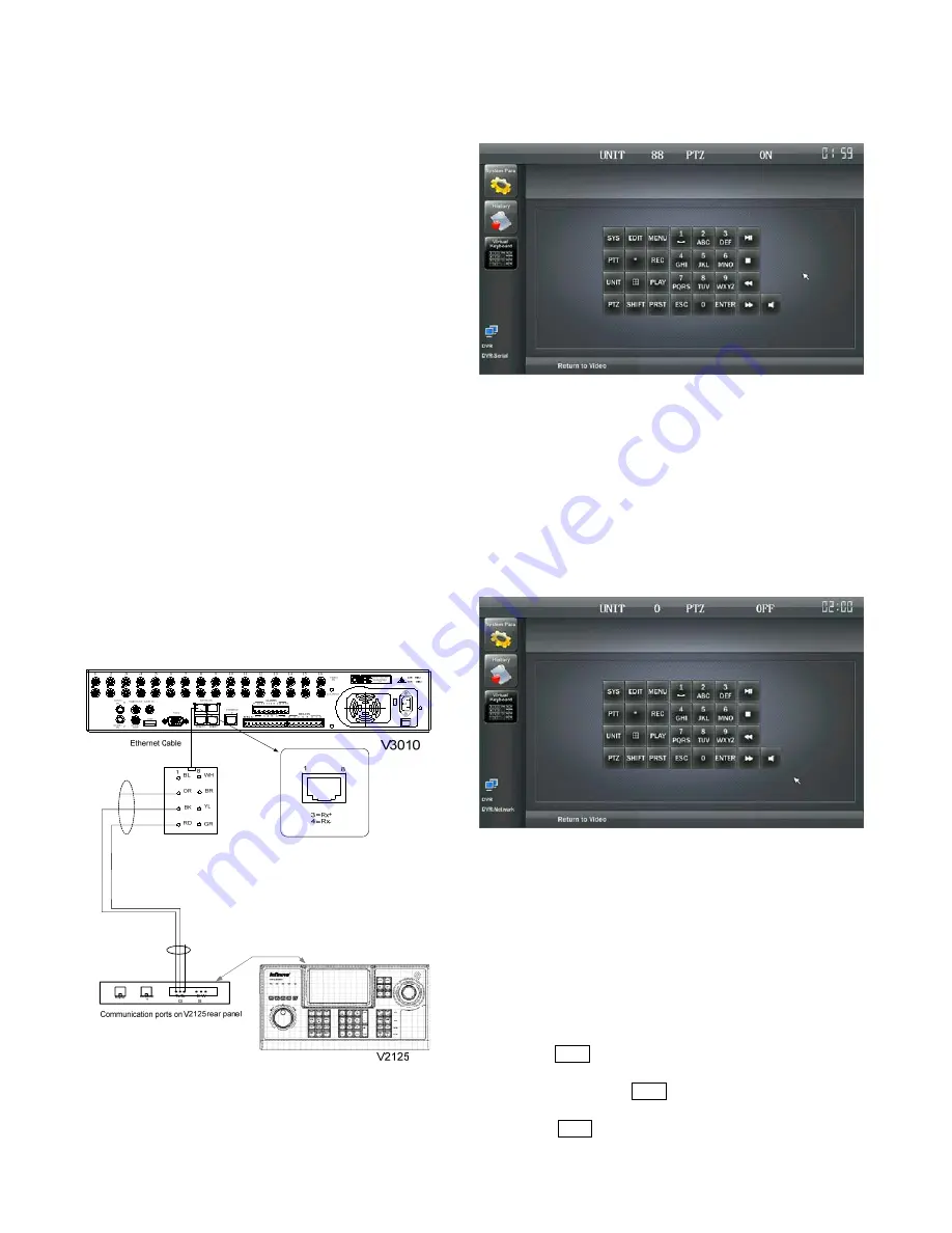
This section will take Infinova V3010/16L as example, to illustrate 
the connection between DVR and V2125 keyboard. 

1.


Use the cables made by our company. Connect one end to 
RS-422/485 port on the V2125 series keyboard. 

2.


Connect another end to the keyboard interface on V3010 
real panel (RJ45 connector). 

For detailed connections, please refer to the figure below:


Figure 5-1. Typical Connection Diagram 


5.3 DVR Operation 

1. RS-422/485 Control Mode 


UNIT:

 indicate DVR number; 

PTZ: 

indicate PTZ status. Options are OFF and ON. The PTZ 

function can be enabled by PTZ key and disabled by ESC key. 
To change DVR number, press the "UNIT" key on keyboard or click 
"UNIT" on the virtual keyboard, and the "UNIT" on the LCD will 
blink. And then enter the desired number on the keyboard, such as 
88. After that, press "UNIT" key again, the UNIT number will be 
changed to 88. 
 

2. Ethernet Control Mode 


UNIT:

 indicate DVR number; 

PTZ:

 indicate PTZ status. Options are OFF and ON. The PTZ 

function can be enabled by PTZ key and disabled by ESC key. 


5.3.1 Select the Controlled DVR 

Multiple DVR units could be controlled by one keyboard in the 
system. To control a specific DVR, user should select the device ID 
that DVR corresponds to. For example, follow the steps below to 
select device ID as "1". 

1.


Press UNIT key on the keyboard, and the characters "UNIT" 
will blink which indicates DVR device ID can be entered; 
while pressing the UNIT key again, the characters "UNIT" 
will stop blinking, which indicate finishing operation; 

2.


Press UNIT key on the keyboard, enter the device ID of 

Summary of Contents for V2125 Series

Page 1: ... audio communication between keyboard to keyboard and among IP front end devices can be realized V2125 series system keyboards can establish Ethernet or RS 232 communications with Infinova series matrix switching systems Eight different baud rates are provided to meet various requirements The system keyboards also feature built in RS 422 485 and Manchester control code generators for direct contro...

Page 2: ......

Page 3: ...em keyboards all comply with Part 15 of the FCC rules Operation is subject to the following two conditions z This device may not cause harmful interference z This device must accept any interference received including interference that may cause undesired operation V2125 series system keyboards have been tested and found to comply with the limits for Class A digital device pursuant to Part 15 of t...

Page 4: ...nded by manufacturer z Position power source and related wires to assure they will be kept away from ground and access way z Refer all service matters to qualified personnel z Save product packaging to ensure availability of proper shipping containers for future transportation Indicates that the un insulated components within the product may carry a voltage harmful to humans Indicates operations t...

Page 5: ...Splitting and Calling Sub screen 14 4 5 1 Screen Splitting 14 4 5 2 Select Sub screen 14 4 6 Operation Mode of Matrix 14 4 6 1 Camera Control 14 4 6 2 Running a Tour 14 4 6 3 Calling a Preset 15 4 6 4 Calling a Salvo 15 4 6 5 Calling a Pattern 15 4 6 6 Activating Auxiliary Relays 15 4 6 7 Acknowledging an Alarm 15 4 7 Program Mode of Matrix 16 4 7 1 System Reset 16 4 7 2 Arranging Monitor Display ...

Page 6: ......

Page 7: ...lish Ethernet or bi directional RS 232 communications with Infinova series matrix switching systems Eight different baud rates are provided to work with different major matrix switcher controllers They also offer five LEDs indicating running status of the system The LEDs from left to right are POWER RS232 RS 485 MANCHESTER and ETHERNET 1 2 Model V2125 System keyboard 7 0 LCD screen 3 D joystick DV...

Page 8: ...em Keyboard Rear Panel Communication ports on the rear panel of V2125 series system keyboard are shown as Figure 2 1 1 In serial number the three pins respectively labeled B W and S are used for direct control of decoders or dome cameras via Manchester control code 2 In serial number the three pins respectively labeled G T and T are provided for direct control over decoders or dome cameras or DVR ...

Page 9: ... shall be 4 to 5 receivers whose ID fall within the scope of 1 64 in addition V2125 can work with V2412M series to provide control of up to 16 receivers Please refer to V2412M series user documentation for more information Figure 2 4 and Figure 2 5 shown below illustrate the connections with the receivers Figure 2 4 Control Receivers via Manchester Code P O W E R C O D E R E F P A N 1 P O T P A N ...

Page 10: ... 230VAC 50Hz NC NO CN RS485 T T GND DATA LINE V2015 Hub Communication ports on V2125 rear panel T T G B W S ETHERNET RS232 V2125 keyboard Figure 2 7 Connect V2015 via Ethernet Communications 2 5 Using Port Expanders In some applications V2405A 4 series Port Expanders might be required to expand the original RS 232 ports of the matrix switching system A single port expander can expand one original ...

Page 11: ...low information before system operation and programming All below menus are operated by mouse or screen touch 3 1 LCD Display Main Interface After the keyboard starting when the power is on video interface will appear soon while the size of video interface is smaller than LCD s Analog or network video interface will be displayed in normal conditions while NO VIDEO will be displayed when the video ...

Page 12: ... The lower left corner will display indicating that the network is disconnected either in Matrix or DVR mode 3 2 System Parameter Setup Click System Para to display the following validation menu for PIN code as shown below Enter system setup menu after the PIN code is entered Super PIN code is 999999 by default PIN code modification is permitted in System Para menu Setup like Basic Para Input Mode...

Page 13: ... Click OK to save the settings otherwise click Cancel Note PIN code is fixed as 6 digits Super PIN code password is 999999 User can enter the System Parameter to set the menu with the Super Password when the user defined password is forgotten Then setup interface in WEB page is displayed below Figure 3 1 Basic Parameter Setup Keyboard function mode can be set here DVR mode or Matrix Dome Mode as w...

Page 14: ...own list Matrix default IP address 192 168 0 1 Note Factory default set of V2125 is Matrix mode Protocol I Baud Rate 1200 When Protocol II is selected communication method defaults to RS422 Baud Rate 9600 Configuration interface at WEB page is shown below Figure 3 3 Matrix Control Setup 3 2 4 Dome DVR Control Click or touch Dome DVR Control to enter Dome DVR control menu If DVR Mode is selected in...

Page 15: ... Audio Intercom Device Type with New System Keyboard or IP Front end optional aim to realize audio intercom among keyboards and from keyboard to IP front end Currently N series SD front ends and N series encoders under Infonova protocol are supported 3 Video IP set the IP address of the devices from which the video sources with 192 168 0 3 by default Currently N series SD front ends and N and K se...

Page 16: ...records While once the records excess 10000 system will update the latest records and delete earlier records as shown below History management includes search history and delete history at WEB page Search History Figure 3 8 Search History User can search or print keyboard operations or set content for a time period Delete History Figure 3 9 Delete History User can delete keyboard operations or set...

Page 17: ...erface will be displayed as below Figure 3 11 Home Page of Web Interface Of which Log Off Write off the current login and return to login interface Sync Time Synchronize with local PC time Help Obtain detailed solutions 3 5 2 WEB User Management To assure system security user needs to input the correct Username and Password to access Web Server User can browse modify and delete user information in...

Page 18: ...3 15 Upload and Backup User can update V2125 keyboard through the latest software package obtained from Infinova s website and other place Under the condition of not changing current system configuration user could update the system through webpage but user shall restart the system to make the software took effect when upload finished After finishing parameter configuration and saving them to FLAS...

Page 19: ...ommunication Route the Ethernet port on the rear panel of V2125 via Hub to the Ethernet port on the matrix switching system as shown in Figure 4 2 Figure 4 2 Connect V2125 with HUB 4 2 User Login To assure system security certain matrix models V2040 for example require a User Login procedure to access system functions Under such circumstances it will prompt Enter Username and Enter Password messag...

Page 20: ...mber 4 Press the MON key to call the sub screen For example press 9NEAR 16MON the number 16 sub screen of number 9 monitor will be selected and then press 9NEAR 8MON the number 8 sub screen of number 9 monitor will be reselected 4 6 Operation Mode of Matrix 4 6 1 Camera Control The real time video from the camera and the relevant system information will be displayed on the monitor after the desire...

Page 21: ...n permits the simultaneous display of multiple camera scenes on a group of contiguous monitors providing surveillance over multiple sites at the same time To call a Salvo 1 Call the first monitor for the desired system salvo 2 Enter the system salvo number on the numeric keypad 3 Press the SALVO key to run the salvo Note Salvos can be automatically called from system tours alarm contacts and other...

Page 22: ...sing the keypad enter a number between 1 and 60 to set the dwell time for the on screen camera To stop and hold the tour on that camera enter 61 6 Once the desired dwell time has been entered press the PROG key to save it The on screen display will then show the time or HOLD if 61 was entered in Step 5 If no more cameras are to be included in the tour skip to step 9 otherwise continue with Step 7 ...

Page 23: ...the PROG position 2 Enter the pattern setting number and then press PATRN key 3 Use the joystick to change the pan tilt and lens positions for the desired pattern 4 Enter and save the pattern number and then press the PATRN key to end the pattern setting process Note different protocols may have different preset number and pattern number please refer to each protocol 4 7 8 Camera Lockout In many s...

Page 24: ...op HMACRO Macro No N A N A Table 4 1 Macro Command Format for Macro programming Command Parameter 1 Parameter 2 Parameter 3 Enter line feed tab and space are allowed in front of each command Only space and tab are allowed between parameter and comma The parameters are identified with a comma in between For example SWITCH 12 22 34 SWITCH 22 44 Each command is ended with line feed There s no capital...

Page 25: ...ch is the default saving position Refer to formats below to edit Macro in text MACRO Macro number NAME Macro name CMD Macro command END User must program in sequence as above There s no capitalization requirement for the aforementioned MACRO NAME CMD and END Only space enter line feed and tab are allowed in front of MACRO Only space and tab are allowed between MACRO and Space enter line feed and t...

Page 26: ...ace on V3010 real panel RJ45 connector For detailed connections please refer to the figure below Figure 5 1 Typical Connection Diagram 5 3 DVR Operation 1 RS 422 485 Control Mode UNIT indicate DVR number PTZ indicate PTZ status Options are OFF and ON The PTZ function can be enabled by PTZ key and disabled by ESC key To change DVR number press the UNIT key on keyboard or click UNIT on the virtual k...

Page 27: ...rd makes video image fast backward while turning rightward makes video image fast forward during playback Rotate the inner ring to adjust frame rate put forward to make the frame rate bigger put back to make the frame rate smaller Appendix I Specifications General Commnunication Protocol RS232 RS422 485 Ethernet Matrix Dome Output Manchester RS 422 485 RS232 Selectable Baud Rate 1200 2400 4800 960...

Page 28: ...ameter shall be 0 8000mm A lower diameter value tends to cause voltage loss and even system instability 0 8000 1 000 1 250 2 000 10 283 86 451 137 716 218 1811 551 20 141 42 225 68 358 109 905 275 30 94 28 150 45 238 72 603 183 40 70 21 112 34 179 54 452 137 50 56 17 90 27 143 43 362 110 60 47 14 75 22 119 36 301 91 70 40 12 64 19 102 31 258 78 80 35 10 56 17 89 27 226 68 90 31 9 50 15 79 24 201 6...

Page 29: ... Use shielded cables or thread the cables through metal tubes for burial thus to ensure the electric connection to the metal tube In case it s difficult to thread the cable through the tube all the way it s acceptable to use tube threaded cables only at both ends of the transmission line yet the length in burial should be no less than 15 meters The cable sheath and the tube should be connected to ...

Page 30: ...Infinova 51 Stouts Lane Monmouth Junction NJ 08852 U S A Tel 1 888 685 2002 USA only 1 732 355 9100 Fax 1 732 355 9101 sales infinova com V1 4 1310 ...

Reviews: