110K(i) 50 Hz Power Conditioner | Owners Manual
8
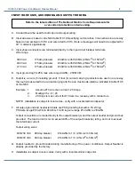
Refer to the latest edition of The National Electric Code Requirements for
over-current protection and wire sizing.
INPUT WIRE SIZE, GROUNDING AND OUTPUT WIRING
A. Conduit should be used for both input and output wiring.
B. Input wire size is based on the NEC table 310.16. Specifying not more than 3 connections in a raceway
based on an ambient of 30°C and wire rated for 90°C (Note: amperages will need to be adjusted for
40° C ambient applications).
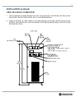
C. Input phase conductors are terminated directly to the input circuit breaker terminals.
Wire range:
380 VAC
175 Amp breaker
#4 AWG to 350 KCMIL (25mm2 to 150mm2)
400 VAC
175 Amp breaker
#4 AWG to 350 KCMIL (25mm2 to 150mm2)
415 VAC
175 Amp breaker
#4 AWG to 350 KCMIL (25mm2 to 150mm2)
D. Input ground lug TA-250, max wire range 6 AWG - 250 MCM.
E. Output is a 4 wire (5 including ground). If four (4) current carrying conductors are used in a raceway
the neutral is assumed to be current carrying and the wire must be de-rated as indicated in table 310.6
on the NEC.
Example: 1.
Assume #10 wire max current = 25 Amps.
2.
Multiply 25 x .8 = 20
3.
20 Amps is max current for #10 wire in a raceway with 4 conductors.
NOTE: Installation is subject to local codes - verify with a local electrical inspector.
F. All output ground and neutral terminals are PK9 grounding bar with a TA 2/0 lug.
PK9 wire range #14 AWG to #4 AWG. TA 2/0 lug wire range #14 AWG to 2/0AWG.
Output connections are made directly to the output breaker(s) and the output neutral and ground bus
provided. The load current is not to exceed 80% of the output breaker(s) rating, and not to exceed
the rated total current.
Output wiring sizes:
400/230 VAC 80 Amp breaker
#14 AWG to 1/0 (2.5mm2 to 50mm2)
400/230 VAC 60 Amp breaker
#14 AWG to 1/0 (2.5mm2 to 50mm2)
G. Output neutral to ground bonded during manufacturing of the power conditioner. Output Neutral is
already grounded by the factory.
H. Installation is subject to local codes. Verify with a local electrician inspector.
Summary of Contents for Transtector 700 A/VS Series
Page 21: ...21 1402 001 APPENDIX A RELATIVE DRAWINGS SCHEMATICS...
Page 27: ...27 1402 001 NOTES...
Page 28: ......


