background image

3

1402-001

RECEIVING & INSPECTING THE UNIT

INSPECTING THE POWER PROCESSOR

Upon receipt of the unit, visually inspect for shipping damage.  If any damage is found, the Purchaser 

must contact the Carrier immediately and file a shipping damage claim.

NOTE:

  Be sure to remove the front and side panels, and inspect the inside of the unit for shipping damage.

If any internal damage has occurred or any external damage that could affect the operation of the unit, 

please contact Transtector.

FOR ASSISTANCE CALL 1-800-882-9110 X 6112 (8am-5pm Pacific Time)

AFTER HOURS CALL 1-800-521-4792

STORING

If it is necessary to store the unit for a period of time before it is installed, be sure to place the unit in a 

clean, dry area.  To prevent excessive dust from accumulating on the unit, it is advisable to protect it by 

replacing it in the original container (if possible). If the original container is not available it is recommended 

that all openings that lead internally into the unit are covered so that dust, water or any other substance 

cannot enter the internal components of the system.  The unit must be handled at all times with the same 

care you would give to any piece of precision industrial equipment.

REMOVING THE POWER PROCESSOR FROM PALLET

Please take special care when removing the unit from the pallet.  Proper equipment must be used for 

lifting and moving, and all safety precautions should be taken.  Each unit is bolted to a wooden pallet. 

In order to properly remove the cabinet from the pallet, all bolts connecting the unit to the pallet must be 

removed completely.  The unit can then be lifted off the skid using a pallet jack or a fork lift, as shown 

below.  When lifting the unit off of the pallet, be sure to take proper safety precautions. Serious injury and/

or unit damage can result otherwise.

Summary of Contents for Transtector 700 A/VS Series

Page 1: ...nditioner with Voltage Regulation 50 Hz Owners Manual Dual Output Power Conditioner with Voltage Regulation 110K i 50 Hz Model Front Access Design Important safety instructions save these instructions...

Page 2: ...Preliminary Installation 6 7 Weights BTU and Dimensions 7 Input Wire Size Grounding and Output Wiring 8 9 Installation 10 13 Bypass Switch 14 Start up 15 Preventive Maintenance 16 Performance Checklis...

Page 3: ...t by replacing it in the original container if possible If the original container is not available it is recommended that all openings that lead internally into the unit are covered so that dust water...

Page 4: ...regulator assemblies and transformer The main AC input circuit breaker must be turned off in order to reset the ALERT light PROTECTION Protection is accomplished very effectively to minimize failures...

Page 5: ...IONS CAUTION RISK OF ELECTRICAL SHOCK AND HIGH SHORT CIRCUIT CURRENT THE FOLLOWING PRECAUTIONS SHOULD BE OBSERVED WHEN WORKING ON THE UNIT 1 REmOvE wATChES RINgS OR OThER mETAL ObjECTS 2 USE TOOLS wIT...

Page 6: ...in a clean dry place with enough clearance to allow a free flow of air Allow a minimum of 36 in front of the 700A VS for installation operation and maintenance There is no clearance required on eithe...

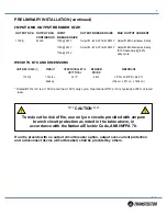
Page 7: ...ded by others OUTPUT KVA OUTPUT KVA CONTINUOUS INPUT BREAKER SIZE OUTPUT BREAKER SIZE MAX OUTPUT CURRENT 110 K I 50 kVA 175A 380 V 175A 400 V 175A 415 V Output 1 80 A 3P for 400 230V Output 2 60 A 3P...

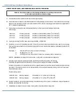
Page 8: ...g conductors are used in a raceway the neutral is assumed to be current carrying and the wire must be de rated as indicated in table 310 6 on the NEC Example 1 Assume 10 wire max current 25 Amps 2 Mul...

Page 9: ...FPA 70 article 250 20 Alternating Current Circuits and Systems to be grounded article 250 20 d Separately derived Systems and article 250 30 grounding Separately derived Alternating Current Systems Th...

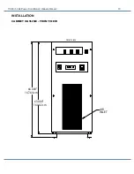
Page 10: ...110K i 50 Hz Power Conditioner Owners Manual 10 INSTALLATION CABINET OUTLINE FRONT VIEW 63 000 66 000 AIR INLET FRONT VIEW 160 02 cm 167 64 cm...

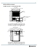
Page 11: ...USING OPTIONAL SIDE OUTPUT TERMINATION NO CLEARANCE REQUIRED ON LEFT SIDE OF UNIT OPTIONAL 12 CLEARANCE ON RIGHT SIDE OF UNIT IF USING OPTIONAL SIDE OUTPUT TERMINATION 3 875 24 750 2 125 0 562 30 750...

Page 12: ...NO CLEARANCE REQUIRED IN BACK OF UNIT NO CLEARANCE REQUIRED ON RIGHT OR LEFT SIDES OF UNIT OPTIONAL 12 CLEARANCE ON RIGHT SIDE OF UNIT IF USING OPTIONAL SIDE OUTPUT TERMINATION 4 500 2 812 4 750 8 25...

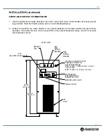
Page 13: ...utput neutral and ground bus provided The load current is not to exceed 80 of the output breaker s rating and not to exceed the rated total current 63 000 66 000 TVSS MOUNTED TO MID PANEL BYPASS SWITC...

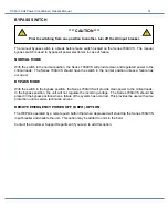
Page 14: ...al position unless a failure has occurred BYPASS MODE With the switch in the bypass position the Series 700A VS will provide clean power to the critical loads In the bypass position the unit will not...

Page 15: ...r 4 Turn on the main AC input breaker 5 Verify that the output voltage is within the specified range 6 Verify output phase rotation is correct 7 Turn the system off 8 Connect the loads one at a time a...

Page 16: ...ed contact Transtector for service 3 A simple performance checklist has been developed for use in maintenance See Performance Checklist and check off items 1 7 4 After items 1 7 have been checked on t...

Page 17: ..._Fan Connections______Transformer Connections 7 Exercise all circuit breakers ______Input Breaker______Output Breakers 8 Input Output Voltage Checks Adjust as Needed No Load Input No Load Output A B__...

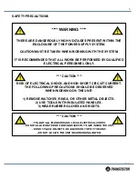
Page 18: ...ITHIN THE ENCLOSURE OF THE POWER SUPPLY SYSTEM CAUTION MUST BE TAKEN WHEN WORKING WITH THE ENCLOSURE IT IS RECOMMENDED THAT ALL WORK BE PERFORMED BY QUALIFIED ELECTRICAL PERSONNEL ONLY Rick Ribbeck Ph...

Page 19: ...CONTROL RELAY 1 13696 13696 13696 PILOT LIGHT RED 3 203943 203943 203943 SENSE BOARD 3 25723 25723 25723 SNUBBER BOARD 3 419721 419721 419721 MAIN CONTROL BOARD 3 108888 108888 108888 PILOT LIGHT GRE...

Page 20: ...r GOLD PLUS PLAN Factory servicemen are not included in this warranty This Warranty is in lieu of all other warranties expressed or implied The giving of or failure to adhere to any advice or recommen...

Page 21: ...21 1402 001 APPENDIX A RELATIVE DRAWINGS SCHEMATICS...

Page 22: ...CE REQ D FRONT SIDE FOR SERVICE OF REGULATOR SECTION REAR VIEW LEFT SIDE 80A 400V OUTPUT BREAKER TVSS BREAKER 1 ADDED 400VAC 380VAC INPUT TO TITLE BLOCK T S 10 9 07 R SUPERIOR SURGE SUPPRESSION Hayden...

Page 23: ...ION ACCESS AREA RIGHT SIDE AIR FLOW R SUPERIOR SURGE SUPPRESSION Hayden Lake ID 83835 419817 0 T SZWAST 8 27 07 OUTPUT VOLTAGE 230 400 VAC INPUT VOLTAGE 415 400 380VAC 8 F R Q SW 110K I 7A VS SLIM 0 2...

Page 24: ...Hayden Lake ID 83835 419817 0 T SZWAST 8 27 07 OUTPUT VOLTAGE 230 400 VAC INPUT VOLTAGE 415 400 380VAC 8 F R Q SW 110K I 7A VS SLIM SERIES 700A VS FRONT ACCESS CABINET OUTLINE 3 3 MATERIAL SCALE TOLER...

Page 25: ...1 lbs Wp min 1065 9 lbs Vertical Force Fp 0 45 x 1442 1 648 9 lbs Moment Fp 0 15 x 1442 1 216 3 lbs Mo 30 x 648 9 15818 0 in lbs Corners a b 39 5 V1 V4 19 3 in Tension Fp x Cg V4 1585 3 lbs Shear Wp...

Page 26: ...ming the process required in this manual Damage to the unit or personal harm could happen if proper precautions are not taken This symbol indicates that there is a risk of electrical shock if proper p...

Page 27: ...27 1402 001 NOTES...

Page 28: ......

Reviews: