background image

InfiNet Wireless Router 


Quick start guide 


Copyright © 2004-2006 by InfiNet Wireless Limited. 

23 

IV.Point-to-Multipoint configuration 

Generally,  point-to-multipoint  configuration  is  NO  different  from  point-to-point 

configuration in terms of devices configuration. This flexibility is obtained due to 
common  hardware/software  platform  used  in  InfiNet  Wireless  routers.  Thus, 

before reading this section of the Guide one MUST read carefully Point-to-Point 

Configuration section in order to set up connection between the Base Station and 
one CPE. In our next example we will add one MORE CPE to the network. If you 

want to add more CPEs please follow the procedure described a desired number 

of times. 
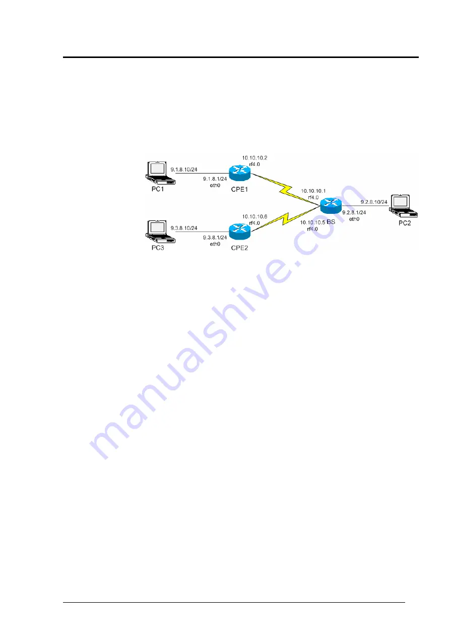
Let us look at the Figure 31 that shows our network design. 


Figure 31. PTM network design 

Here we have added another CPE (CPE2) from a different network. No need to 

have  a  detailed  description  of  each  step  to  be  taken  as  all  of  them  were 

discussed in the previous chapter. The steps to be taken are the following: 
1. Get access to the router (CPE2) from PC3. 
2. Configure BS router’s CPE table for the CPE2. In order to do that learn CPE2 

MAC-address for the radio (

ifc -a

 command). On the BS execute the following 

command: 

rma ab rf4.0 <MAC> ip=10.10.10.5 name=CPE2 

<MAC> - is a MAC-address of CPE2 radio interface.  
10.10.10.5 – IP-address of the BS connection with CPE2 from the side of 

BS. CPE will be automatically assigned next IP-address for its connection 
with BS after its registration. 

3. Configure BS at the CPE side. It should be done in the same way as we did for 

the first CPE: 

rma rf4.0 20202020/24000 5300 

Requested  speed  (here 

24000

)  may  differ  according  to  the  CPE 

capabilities and your network design. 

4. Run RMA at the CPE: 

rma start 

5.  After  some  time  (several  seconds)  the  CPE  will  register  at  BS  (if  the 
configuration  was  accomplished  correctly).  To  learn  that,  type 

rma  bs

  at  the 

CPE side (you will see BS parameters) and 

rma ab

 at the BS side (you will see 

whether this CPE is registered or not). 
6. Run RIP protocol on CPE (

rip start

7. Provide PC3 connectivity from all nodes of the network. Write corresponding 

routes on all PCs. For PC1 and PC2 it will be a route to 

9.3.8.0/24

 network. On 

PC3 it will be routes to 

9.2.8.0/24

 and 

9.1.8.0/24

 network. If you use 

eth0


address of the router as a 

default gateway

 for the PC you do not have to write 

routes. 
Note  that  BS  throughput  will  be  redistributed  between  CPEs  according  to 
different criteria, including their connection speed with BS and QoS rules (if any). 
 

Summary of Contents for R5000-L

Page 1: ...Copyright 2004 2006 by InfiNet Wireless Limited 1 Updated 24 April 2006 InfiNet Wireless Router Quick start guide...

Page 2: ...Copyright 2004 2006 by InfiNet Wireless Limited 2 Copyright 2004 2006 by InfiNet Wireless Limited All rights reserved...

Page 3: ...viations 7 3 Document marks 8 4 Additional information 8 II GETTING ACCESS TO THE ROUTER 9 1 PC Laptop LAN connection 9 Cabling lab 9 Accessing the router via Console 10 Accessing the router via Ether...

Page 4: ...er Quick start guide Copyright 2004 2006 by InfiNet Wireless Limited ii VI CONNECTORS SOLDERING SCHEMES 27 1 Service cable connector soldering scheme 27 2 Console cable connector for 5000 M and 5000 O...

Page 5: ...manual may cause harmful interference to radio communications Operation of this equipment in a residential area is likely to cause harmful interference in which case the user will be required to corre...

Page 6: ...such that it does not emit RF fields in excess of Health Canada limits for the general population consult Safety Code 6 obtainable from Health Canada s Web site www hc sc gc ca rpb Avis de conformit...

Page 7: ...y 2 Installation External antennas for InfiNet wireless equipment must be professionally installed due to the hazards involved in installation of equipments on towers building exteriors and rooftops A...

Page 8: ...pyright 2004 2006 by InfiNet Wireless Limited 6 Waves Sector SEC 5V 90 17 Radio Waves 5 725 5 850 17 0 dBi Yes N A N A Sector TA 5705H 14 90 Til Tek 5725 5875 16 5 dBi Yes N A N A Sector SAH58 90 Paci...

Page 9: ...difference between PTM and PTP topology when building a network based on InfiNet Wireless Routers Due to similarity of PTM and PTP configuration it mostly references a previous chapter Performing outd...

Page 10: ...s written in the Warning sections All notes are marked with a special note sign Notes usually contain useful comments or hints to the described section of the document 4 Additional information Additio...

Page 11: ...ack the equipment 2 If you do not have a service cable soldered please do it using special connectors included into the package according to the soldering scheme located in the Supplementary informati...

Page 12: ...ps described in this section your PC Laptop must be equipped with a COM port 2 Locate the power cord in the package 3 Plug the power cord into the IDU power supply connector and to the power supply so...

Page 13: ...lected the right port and made its configuration right after pressing enter on the white blank screen after step 8 you should see WANFleX OS prompt as shown on Figure 7 Figure 7 WANFleX OS prompt 10 Y...

Page 14: ...ter Do not forget to save your configuration using co sa config save command Figure 9 Changing IP address on eth0 interface 12 If all your settings are correct you can connect the router to your LAN u...

Page 15: ...ection and click Properties See Figure 12 Figure 12 LAN Connection properties 4 Choose Internet protocol TCP IP and click Properties See Figure 13 Figure 13 Internet Protocol Properties 5 If you want...

Page 16: ...TCP IP Settings click Add and put alias IP address and mask e g 10 10 10 2 and 255 255 255 0 correspondingly See Figure 15 Click OK in all windows opened in the described procedure Figure 15 Create a...

Page 17: ...um number of concurrent Telnet sessions per one router is five System parameters Once you ve got access to the router the most common thing to be done in the first turn is to set up some basic system...

Page 18: ...r levels bitrates for the specific radio interface rf IF NAME cap command is used For example rf rf4 0 cap See Figure 18 Figure 18 Router s capabilities Radio module parameters configuration 1 Power l...

Page 19: ...f4 0 freq 5300 Configure SID system identifier system identifier of the router a hexadecimal number in the range of 1H to FFFFFFH All routers that are supposed to see each other on the same radio link...

Page 20: ...autobitrate mechanism is used see below this value will set the minimal value for the bitrate This parameter is optional If skipped the lowest available bitrate will be used SPEED BS requested connect...

Page 21: ...t In our case the table looks as shown on Figure 21 if CPE is registered and as shown on Figure 22 if CPE is not registered The command to view BS table is rma ab Figure 21 BS table with registered CP...

Page 22: ...iding PC LAN connectivity Once radios see each other we need to make our LAN PC Laptop see each other also The best thing that should be done in the first turn is to turn on dynamic routing on both of...

Page 23: ...tables formed using RIP protocol the packet will be sent via radio to the CPE router After that CPE router will look up in its routing tables and send the packet through its Ethernet interface to the...

Page 24: ...e remote computer Enter login and password for the FTP server Run several FTP streams from the remote computer In order to do that create several FTP sessions according to the procedure described in t...

Page 25: ...e radio ifc a command On the BS execute the following command rma ab rf4 0 MAC ip 10 10 10 5 name CPE2 MAC is a MAC address of CPE2 radio interface 10 10 10 5 IP address of the BS connection with CPE2...

Page 26: ...Distance setting For outdoor testing deployment it is vitally important to set up distance parameter correctly The recommended procedure is the following 1 If the you have a PTP topology on the BS you...

Page 27: ...gnal levels are not enough signal levels according to InfiNet scale are meant in the case antenna alignment procedure is strongly recommended In both cases whether there is a registration or not the f...

Page 28: ...ode is recommended to see the activity on all available for your radio frequencies muffer rf4 0 review Figure 33 shows a sample output for this command Figure 33 Muffer review mode On the figure we ca...

Page 29: ...InfiNet Wireless Router Quick start guide Copyright 2004 2006 by InfiNet Wireless Limited 27 VI Connectors soldering schemes 1 Service cable connector soldering scheme...

Page 30: ...InfiNet Wireless Router Quick start guide Copyright 2004 2006 by InfiNet Wireless Limited 28 2 Console cable connector for 5000 M and 5000 O soldering scheme...

Reviews: