


User Manual
16 of 37
Revision 1.0
2018-08-23
EVAL-M1-CTF620N3 User Manual
iMOTION
™
Modular Application Design Kit
Getting Started with EVAL-M1-CTF620N3
After Drive System Parameter file has been programmed into IMC102 controller, and the motor drive system is
powered, the MCEDesigner can be used to start/stop the motor, display motor current traces, change the motor
speeds, modify drive parameters and many other functions. Please refer to the MCEDesigner documentation
for more details.
Note:
On-board Debugger portion of EVAL-M1-101T is galvanically isolated from the controller portion
and the attached power board. In order to program the parameters or firmware to the IMC101T-
T038 controller, the 3.3V DC voltage needs to be supplied to the controller portion of the EVAL-M1-
101T. This voltage can either be supplied by the power board (MADK power boards are designed to
supply the 3.3V to the control board through M1 connector) or by feeding the 3.3V DC voltage to the
control board through some of the available 3.3V access/test points if the power board is not
attached to the EVAL-M1-101T control board.
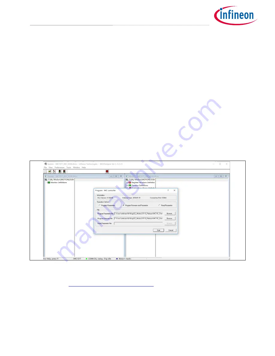
To program new firmware and Drive System Parameter into IMC101T-T038, please click “Tools” menu and
select “Programmer” in the pull down list. The pop-up window “Program IMC controller” will show up as in
Figure 10. Click on the “Program Firmware and Parameter” radio button, and select the Drive System
Parameter file created using MCEWizard by clicking on the “Browse” button on the row of “Program Parameter
File”, and then select the firmware file by clicking on the “Browse” button on the row of “Program Firmware
File”. Finally, click on the “Start” button to program the parameter file into the IMC101T-T038 IC.
Figure 10 Program Firmware and Parameter in “Program IMC Controller” pop-up window
All latest firmware file for different type of iMOTION
TM
control ICs are available for download via Infineon
iMOTION
TM
website (
http://www.infineon.com/imotion-software
).