Application Note
20
Revision 1.0
2017-11-15
1200V HighSpeed 3 IGBT in TO-247PLUS Evaluation Board
User Manual
Appendix
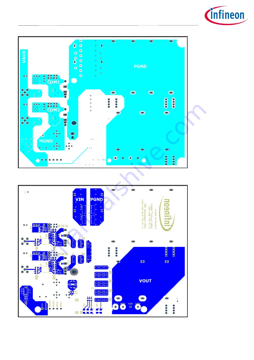
Figure 16 Layer 3
Figure 17 Layer 4 (bottom layer)
Page 1: ...ers and users of the evaluation board Table of Contents About this document 1 Table of Contents 1 1 Introduction 3 1 1 Purpose of the board 3 1 2 Scope of delivery 4 2 Hardware 5 2 1 Circuit and main...
Page 2: ...al contact during operation might result in severe injury or death Always make sure that the capacitors are discharged before touching the board Only qualified personnel are allowed to handle this boa...
Page 3: ...emitter connection of the TO 247PLUS 4pin package For detailed information on these packages refer to application notes 1 and 2 respectively a b Figure 1 Evaluation board and devices under test a 120...
Page 4: ...ompact isolated gate driver ICs 1EDI60I12AH in a 300mil wide body package USB flash drive containing all related application notes and data sheets Wire to board plugs for connecting the evaluation boa...
Page 5: ...led with independent PWM signals on the connectors SIG HS and SIG LS The driving voltages are provided using the 12V auxiliary supply and isolated DC DC converters For versatility reasons the evaluati...
Page 6: ...ents where extremely steep current slopes of several Amperes per nanosecond are reached An ideal current measurement for this purpose would be non invasive at least it should not require significant c...
Page 7: ...easurements the acquisition of voltage waveforms is straightforward By selecting the emitter potential of the low side IGBT S2 as common ground the gate voltage the collector emitter voltage and the c...
Page 8: ...nd eventually copper pads or traces may lift off and break In order to allow a large number of IGBT and diode replacements this evaluation board uses press fit pins for connecting the TO packages and...
Page 9: ...pins four lead packages to pins 2 5 three lead packages to pins 1 3 2 Ensure that the reference of the driver output is connected to the proper Emitter lead using a 0 resistor assemble R214 R224 for...
Page 10: ...ready contains high accuracy input filters there is no need to use an external RC low pass on the signal path Such a filter would require additional components introduces a higher propagation delay to...
Page 11: ...n be approximated with a thermal resistance of around 6 K W to the ambient and a thermal time constant of approximately 7 minutes This analytic description is valid if the heat sink is facing upwards...
Page 12: ...loss measurements and continuous operation 4 Boost Converter Switch S2 Diode S1 TS1 TS2 Theatsink VCE and VGE waveforms VDC 1 d fsw Pout VGE on VGE off RG Package 900V 1 5 0 5V 12 20V TO 247x 3 4 4 D...
Page 13: ...1 and T2 respectively while the voltage level is set directly with the DC link voltage VDC the current value is adjusted with the width of the first pulse T1 T0 Figure 9 b shows the current value as a...
Page 14: ...sistor E200 and the NTC B200 d Remove the probe adapter Id2 from the board e If necessary solder the film capacitors C203 and C204 to the other side of the board f Mount a reasonable heat sink If poss...
Page 15: ...LUS 4pin Junction temperature Tj Tc 25 C 25 C Switched voltage VCE 800V 800V Switched current IC 5A 80A 5A 80A Gate voltages VGE on 15V 15V Gate resistors RG on 10 10 Driver Ground Connection 0 at R21...
Page 16: ...parability care was taken to scale the semiconductor losses with the respective chip size Besides the output power also the switching speed and the ripple current were adjusted accordingly Table 5 Com...
Page 17: ...allel IGBT which processes another 2kW Assuming perfect current sharing and a constant heat sink temperature the temperature of the second IGBT would be equal to the one of the first Table 6 Results o...
Page 18: ...8 Revision 1 0 2017 11 15 1200V HighSpeed 3 IGBT in TO 247PLUS Evaluation Board User Manual Appendix 5 Appendix 5 1 Schematic drawing Figure 12 Power and driving circuitry Figure 13 Auxiliary supply a...
Page 19: ...Application Note 19 Revision 1 0 2017 11 15 1200V HighSpeed 3 IGBT in TO 247PLUS Evaluation Board User Manual Appendix 5 2 Board layout Figure 14 Layer 1 top layer Figure 15 Layer 2...
Page 20: ...Application Note 20 Revision 1 0 2017 11 15 1200V HighSpeed 3 IGBT in TO 247PLUS Evaluation Board User Manual Appendix Figure 16 Layer 3 Figure 17 Layer 4 bottom layer...
Page 21: ...122 10u X7R 35V C 0805 C123 10u X7R 35V C 0805 C200 470pF C0G 50V C 0805 C201 TDK Z63000Z2910Z 1 Z21 C202 TDK Z63000Z2910Z 1 Z21 C211 4u7 X7R 25V C 0805 C212 4u7 X7R 25V C 0805 C221 4u7 X7R 25V C 0805...
Page 22: ...3473 X205 Wurth Elektronik 93473 X206 Wurth Elektronik 93473 X210 TE Connectivity 5 1814400 1 X220 TE Connectivity 5 1814400 1 X801 Phoenix Contact GMSTB 2 5 HCV 4 ST 7 62 LR 1812775 X802 Phoenix Cont...
Page 23: ...Bergquist Sil Pad K10 MP851 Spring Clip for TO 247 Fischerelektronik THFU 2 MP852 Spring Clip for TO 247 Fischerelektronik THFU 2 MP853 Spring Clip for TO 247 Fischerelektronik THFU 2 MP854 Spring Cli...
Page 24: ...G TRENCHSTOP 5 IGBT in a Kelvin Emitter Configuration Performance Comparison and Design Guidelines Revision 1 0 2014 10 16 3 Markus Billmann Coaxial Shunts Technical Data http www ib billmann de May 2...
Page 25: ...0 2017 11 15 1200V HighSpeed 3 IGBT in TO 247PLUS Evaluation Board User Manual Revision History Revision History Major changes since the last revision Page or Reference Description of change Revision...
Page 26: ...l information given in this application note The data contained in this document is exclusively intended for technically trained staff It is the responsibility of customer s technical departments to e...
Page 27: ...3158YML EV MIC23451 AAAYFL EV MIC5281YMME EV 124352 HMC860LP3E ADM00513 ADM8611 EVALZ ADM8612 EVALZ ADM8613 EVALZ ADP1046ADC1 EVALZ ADP1055 EVALZ ADP122 3 3 EVALZ ADP130 0 8 EVALZ ADP130 1 2 EVALZ ADP...