


Application Note
8 of 36
002-34970 Rev. **
2022-05-03
Foreign object detection tuning guide for wireless power transmitters
Applicable for WLC ICs
Getting started
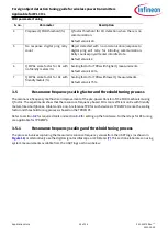
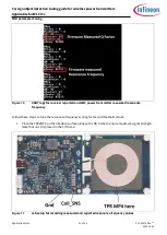
Figure 3
Typical power loss measurement with power delivery range
System power loss:
The FO is detected if the measured system power loss exceeds the system power loss
threshold value. Refer to
for more details on the FOD techniques recommended by the Qi Standard.
Accurate FOD requires reference to the power loss calibrated parameter data for a given hardware design and
interface surface height (Z-axis). This reference calibration data is required to compensate for the power loss
balance deviations induced by the system. The WLC power transmitter system power loss varies with
transmitter power delivery range, receiver device coupling factor, temperature, etc. Section
shows a typical
power loss measurement over the power delivery range and the respective loss correction curve. This is a
typical behavior of loss correction along with the system power losses.
Power loss calculations are initiated on receipt of a RPP. The calibrated transmitter power is derived from RP
value as follows:
P
Tx_calib
=
a
* P
Rx
2
+
b
* P
Rx
+
c
Equation 6
Where
a
,
b
and
c
are the system power loss curve coefficients. These coefficients are unique for each power
transfer mode as follows:
•
EPP 15 watt (EPP15W): Representative test power receiver (TPR) is TPR#MP3. The load power typically
ranges from 300 mW to 15 W.
•
EPP 5 watt (EPP5W): Representative TPR is TPR#7. The load power typically ranges from 300 mW to 5 W.
•
Baseline power profile (BPP): Representative TPR is TPR#5. The load power typically ranges from 300 mW to
5 W.
A
system power loss curve
is used to account for the losses from the transmitter. The power loss equation
relates the transmitter power and the reported power as follows:
P
loss
= P
Tx
– P
Tx_calib
Equation 7
Where P
Tx_calib
is derived from Equation 6. The criteria for FO presence are:
P
loss
>= P
Threshold
Case 1
P
loss
>= P
Threshold_max
Case 2
Where P
Threshold
and P
Threshold_max
are configuration parameters, and:
P
Threshold_max
> P
Threshold
-150
-100
-50
0
50
100
150
200
250
300
0
2000
4000
6000
8000
10000
12000
14000
16000
18000
20000
Los
ses
(m
W
)
PRx (mW)
Measured system power loss
System Power Loss Curve
CorrectedLosses