background image


Application Note 

20 of 36 

002-34970 Rev. **  


2022-05-03


Foreign object detection tuning guide for wireless power transmitters 
Applicable for WLC ICs 
 

FOD parameter tuning 


S. no. 

Parameter 

Description 

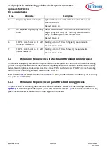
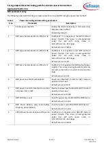
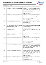
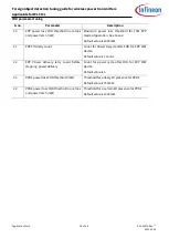
Prepower Q FOD threshold (%) 

Q  factor  threshold  for  FO  detection  when  there  is  no 
communication. 
Default value is 30. 

No  response  digital  ping  retry 
count 

Object  detected  with  no  communication/response  to 
digital  ping  will  retry  for  initiating  communication. 
Retry count expiry will enter into idle state. 
Default value is 2.  

Q  MPA1  scale  factor  for  Rx  with 
no friendly metals (%) 

Scaling factor for TPRs with higher Q measurements.  
Default value is 40%. 

Q  MPA1  scale  factor  for  Rx  with 
friendly metals (%) 

Scaling factor for TPRs with lower Q measurements.  
Default value is 75%. 

3.5


Resonance frequency scaling factor and threshold tuning process


The resonance frequency method is an improvement of the pre-power transfer of the FOD mechanism using 
Q factor. The experiments show that the resonance frequency-based FO is more efficient on Rx with friendly 
metals, like smartphones, tablets and so on. A reference TPR for such devices is TPR#MP4. Hence the scaling 
factor and threshold tuning process is based on the TPR#MP4.  

Refer to section

 3.2

 for required tools and section

 3.3

 for setting up the hardware. Further steps for RF tuning 

are applicable for TPR#MP4.   

3.5.1


Resonance frequency scaling and threshold tuning process  


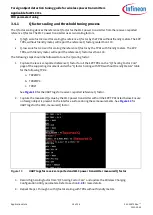
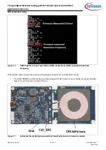
The process involves capturing the measured resonance frequency values from the UART logs (as shown in 

Figure 16)

 or alternatively use the digital signal oscilloscope or LCR Mete

[7]

.This section elaborates on using 

system measurements available from the UART logs as shown below:  

Summary of Contents for AN234970

Page 1: ...ut this document Scope and purpose The wireless charger WLC power transmitter solution reference board is a highly integrated wireless solution with Type C power delivery PD This application note is a guide to configure the foreign object detection FOD parameters required for custom designs based on the WLC power transmitter reference design Intended audience Experts who customize designs based on...

Page 2: ...ctor scaling factor tuning process 17 3 4 1 Q factor scaling and threshold tuning process 18 3 4 2 Q factor based FOD tuning 19 3 5 Resonance frequency scaling factor and threshold tuning process 20 3 5 1 Resonance frequency scaling and threshold tuning process 20 3 5 2 Resonance frequency based FOD tuning 23 3 6 System power loss curve coefficient tuning 23 3 6 1 Data collection and system loss c...

Page 3: ...ded power profile TPR Test power receiver ASK Amplitude shift keying FSK Frequency shift keying WPT Wireless power transfer CE Control error CEP Control error packet FO Foreign object OVP Overvoltage protection OCP Overcurrent protection UVP Undervoltage protection FOD Foreign object detection PCB Printed circuit board EMI Electromagnetic interference NTC Negative temperature coefficient UART Univ...

Page 4: ...lation and updating the WLC power transmitter using the Wireless Charging Configuration Utility This section gives the following details o Q factor scaling factor and threshold tuning This section defines the process for configuring the scaling factor and thresholds for a Q factor based FOD approach o Resonance frequency scaling factor and threshold tuning This section defines the process for conf...

Page 5: ... the negotiation phase The Tx responds to these packets with an ACK packet if no FO is found and with a NAK packet if a FO is found The Rx measures the Q factor and resonance frequency values with a standard MP A1 coil The transmitter may measure Q factor and resonance frequency values different from the receiver reported values as it may have a different coil A scaling factor is used to convert t...

Page 6: ...power transfer starts The FO is detected if the difference between measured and receiver reported reference Q factor FOD qf packet is less than the threshold The measured Q factor includes a scaling factor 7 If Qrep is the receiver reported Q factor and Qscl is the scaled Q factor then Qrep Sfactor Qscl Equation 1 Where Sfactor is the scaling factor for the custom transmitter FO detection occurs w...

Page 7: ...the difference between measured and scaled reference resonance frequency is greater than the threshold ScalingFactor and Threshold_percent are configurable from the wireless charging configuration utility In case of a FOD the Tx responds to the FOD rf or FOD qf packets with a NAK packet leading to immediate power disconnect The communication is re established only after the object is removed Refer...

Page 8: ...s Power loss calculations are initiated on receipt of a RPP The calibrated transmitter power is derived from RP value as follows PTx_calib a PRx 2 b PRx c Equation 6 Where a b and c are the system power loss curve coefficients These coefficients are unique for each power transfer mode as follows EPP 15 watt EPP15W Representative test power receiver TPR is TPR MP3 The load power typically ranges fr...

Page 9: ...tifies the placement of an object and initiates the Qi communication stack which involves pre and in power transfer FOD mechanisms Pre power transfer data is measured by Tx during the analog pings Upon object detection the free air FOD method finds FOs If the device is a valid receiver it proceeds to the identification and configuration phases The FOD qf packet is exchanged for an EPP device optim...

Page 10: ...or WLC ICs Getting started Measure the open air Q factor Is the measured Q less than the open Air FO threshold No Yes FO detected by Q factor Wait till the object is removed LED UI indication Proceed to digital ping 1 BPP and EPP devices Receiver FO arrival detection Figure 5 Procedure for free air Q factor FOD in BPP and EPP devices ...

Page 11: ...ustrates the FOD using Q factor mechanism Continued from 1 EPP device Process the FOD qf packet from receiver Is the measured Q less than the reference threshold NAK the FOD qf packet indicating an FO Yes Valid TPR Smart phone ACK the FOD qf packet No Proceed to next phase Wait till the object is removed LED UI indication Figure 6 Procedure for Q factor FOD in EPP devices ...

Page 12: ...ing the resonance frequency mechanism Continued from 1 EPP device Process the FOD rf packet from receiver Is the difference in RF measurements greater than threshold NAK the FOD rf packet indicating an FO Yes Valid TPR Smart phone ACK the FOD rf packet No Proceed to next phase Wait till the object is removed LED UI indication Figure 7 Procedure for resonance frequency FOD on EPP devices ...

Page 13: ...ing the threshold_ max No Yes Is the loss exceeding the threshold but under Threshold _max Yes No Continue the power transfer FO detected with maximum power loss FO detected with power loss Wait till the object is removed LED UI indication Are the user configured retries complete Yes No Figure 8 Procedure for FOD using power loss mechanism on EPP and BPP devices As shown in Figure 8 the system pow...

Page 14: ...ge The calculations section gives the parameter values for Q factor tuning based on user inputs RF Scaling_Threshold Calc The RF based data is collected in the User Inputs section The scaling factor and threshold frequency are auto generated based on the user data Wireless Charging Configuration Utility will save the configurations to the WLC power transmitter These calculations are taken from FOD...

Page 15: ...approved compliance tester The user may approach the WPC s authorized test labs ATLs 5 in case of unavailability of the compliance tester tools The user should refer to the WPC member login page for details of the list of WPC approved compliance testers The following accessories are available along with the software tool Test power receivers TPRs For the tuning process the following TPRs are neede...

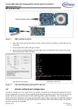
Page 16: ...serial communication based PC tool for capturing UART logs from the WLC power transmitter board ensure that the PC tool used for data logging is capable of processing UART data at 1 000 000 baud with minimal losses 3 3 Hardware setup 1 Enable the UART debugs from the Wireless Charging Configuration Utility See Appendix III for details 2 Connect the UART Tx line from the power transmitter board to ...

Page 17: ...Tera Term screen UART log on Tera Term Figure 12 Tera Term debug screen and log UI for reference 3 4 Q factor scaling factor tuning process Use the QF Scaling Factor Calc page in FOD_TuningGuide_Calculator xlsx as the supporting document for this section Update the User Inputs section with the measured and reported Q Factor values The measured and reported Q Factor values can be taken from the UAR...

Page 18: ... following steps should be followed to tune the Q scaling factor 1 Capture the receiver reported reference Q factor for all the EPP TPRs on the QF Scaling Factor Calc page of the supporting document under the Q factor Scaling with TPRs without Friendly Metals table for the following TPRs a TRP MP3 b TPR MP4 c TPR 7 See Figure 13 for the UART logs for receiver reported reference Q factor 2 Capture ...

Page 19: ... The next section explains the usage of the parameters generated in the supporting document 3 4 2 Q factor based FOD tuning Figure 15 View of Q factor settings configuration tool Table 2 Q factor configuration setting parameters S no Parameter Description 1 Q factor and resonance frequency FOD enable Enables Q factor measurement for FOD Enabled by default 2 Open air coil Q Open air Q factor value ...

Page 20: ...Default value is 75 3 5 Resonance frequency scaling factor and threshold tuning process The resonance frequency method is an improvement of the pre power transfer of the FOD mechanism using Q factor The experiments show that the resonance frequency based FO is more efficient on Rx with friendly metals like smartphones tablets and so on A reference TPR for such devices is TPR MP4 Hence the scaling ...

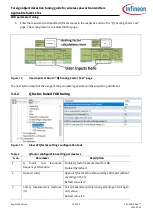
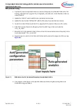
Page 21: ...or receiver reported and WLC power transmitter measured resonance frequency Follow these steps to tune the resonance frequency scaling factor and threshold values 1 Place the TPR MP4 on the interface surface along with FOD frame to ensure maximum signal strength Note that no FO is placed in the FO frame Figure 17 Lab setup for recording measured and reported resonance frequency values ...

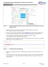
Page 22: ... Without FO with the firmware measured resonant values 5 Insert FO1 to the FO frame such that FO is aligned with the center of the coils of Tx and Rx 6 Enter the measured resonance frequency from the UART logs in the row marked as FO_1_At_0mm 7 Move FO1 to 15 mm marked on the FO frame Enter the measured resonance frequency in the row marked under FO_1_At_15mm 8 Repeat steps 4 5 and 6 for FO2 FO3 a...

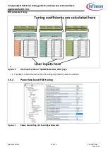
Page 23: ...h TPR 5 This section covers tuning FOD functionality parameters for all three modes of operation System power loss curve coefficient tuning requires a tuning setup based on the user Refer to the WPC member login page for details of the list of WPC approved compliance testers Refer to section 3 2 for the required tools and section 3 3 for details on setting up the hardware Refer to the WPC member l...

Page 24: ...reported receiver power values from the UART debug log to the supporting document 7 Increase the load to the next step Refer to the SystemPowerLoss_data page in FOD_TuningGuide_Calculator xlsx for the next load value 8 Repeat steps 6 7 and 8 until PRx and PTx values are captured for the maximum load value The system power loss curve data for TPR MP3 is ready Figure 21 PTx and PRx values from UART ...

Page 25: ...ess power transmitters Applicable for WLC ICs FOD parameter tuning ss Figure 22 User input section in SystemPowerLoss_data page 11 This data is used in the next section for configuring the WLC power transmitter 3 6 2 Power loss based FOD tuning Figure 23 Power loss settings in the configuration tool ...

Page 26: ...the cell with same name in SystemPowerLoss_data page Default value is 0 9743 4 BPP Loss characterisation co efficient c Coefficient c inEquation 6 for BPPmode of power transfer This value is auto generated under the cell with same name in SystemPowerLoss_data page Default value is 141 48 5 BPP power loss FOD threshold mW Power loss threshold in mW for BPP mode of operation See Case 1 Default value...

Page 27: ...mode of operation See Case 2 Default value is 1000mW 14 EPP 5W FOD retry count Count for power recycle after FOD for EPP 5W device Default value is 3 15 EPP5W Power delivery retry count before stopping power delivery Count for power cycle after FOD for EPP 5W device Default value is 3 16 EPP loss characterisation coefficient a Coefficient a in Equation 6 for 15W EPP mode of power transfer This val...

Page 28: ...tion See Case 2 Default value is 2000mW 21 EPP FOD retry count Count for Power Recycle after FOD for EPP 15W device Default value is 1 count 22 EPP Power delivery retry count before stopping power delivery Count for power cycle after FOD for EPP 15W device Default value is 1 23 PPDE power loss FOD threshold mW Threshold for a likely FO presence for PPDE Default value is 750mW 24 PPDE power loss FO...

Page 29: ...meters for EPP devices 1 MP TX FOD OPERATE FOD REACT TC1 2 MP TX FOD OPERATE FOD REACT TC1a 3 MP TX FOD OPERATE FO CRIT TC1 4 MP TX FOD OPERATE FO CRIT TC1a 5 MP TX FOD BEFOREPOWER FO CRITIC TC1 6 MP TX FOD BEFOREPOWER FO CRITIC TC1a Tests 1 and 2 validate the Threshold_max setting in EPP devices The critical section tests 3 through 6 validate the Q factor and threshold settings Refer to 8 for det...

Page 30: ...ble signal strength alignment between TPR and transmitter Refer to Appendix I for finding the best signal strength 5 Ensure proper offset values are considered while tuning the power loss FOD parameters Refer to Appendix II for more details 6 Ensure that no FO is present on the interface surface or in the vicinity field of influence of the transmitter coil 7 Ensure the FOD functionality is appropr...

Page 31: ...ding signal strength Appendix I Finding signal strength Note This process is unique for every compliance tester 1 Enable the Signal Strength Finder in the compliance tester tool See Figure 24 2 Ensure the TPR is placed at maximum signal strength best alignment with transmitter coil 3 Disable the Signal Strength Finder once the alignment procedure is complete ...

Page 32: ...igure 24 Received Power Offset in Advanced mode The value of Received Power Offset in the Advanced mode operation determines the accuracy of the system power loss coefficients used to calculate the system power loss The default values of received power offset are different for Qi 1 2 and Qi 1 3 and may vary for Qi compliance tests as well as guaranteed power GP tests The following table provides t...

Page 33: ... the UART logs when not needed The standard system behavior is tested with UART logs disabled The UART logs can be enabled by enabling the following parameters in the transmitter Profile page in the Wireless Charging Configuration Utility see Figure 25 UART enable Critical enable Message enable Set Debug enable to Level 1 Figure 25 Profile page settings for enabling UART logs Revert these changes ...

Page 34: ...rt 12 Qi Standard Version 1 2 4 5 External link WPC s list of ATLs 6 Section 5 4 3 3 Part 3 Compliance Testing Qi Standard Version 1 2 4 7 Section 11 3 3 Part 12 Definition of the Reference Quality Factor Qi Standard Version 1 2 4 8 Section 5 4 3 Part 3 Foreign Object Detection Qi Standard Version 1 2 4 9 Reference board REF_WLC_TX15W_C1 wireless power transmitter reference board 10 Product datash...

Page 35: ...970 Rev 2022 05 03 Revision history Foreign object detection tuning guide for wireless power transmitters Applicable for WLC ICs Revision history Document version Date of release Description of changes 2022 05 02 New application note ...

Page 36: ...on note The data contained in this document is exclusively intended for technically trained staff It is the responsibility of customer s technical departments to evaluate the suitability of the product for the intended application and the completeness of the product information given in this document with respect to such application For further information on the product technology delivery terms ...

Reviews: