Inficon RSH-600 Operating Manual Download Page 17

2 – 6

RSH-600 Operating Manual

2.5  Adjustable Flange Installation

1

Apply a small amount of vacuum compatible grease to the entire surface of the 
O-ring that is included with the adjustable flange and then install the O-ring into 
the O-ring groove in the adjustable flange.

2

Loosen the hex socket head screw on the adjustable flange.

3

Remove the cover from the RSH-600 sensor.

4

If the crystal holder contains any crystals, remove the holder and remove and 
discard the crystals. Reinstall the crystal holder.

5

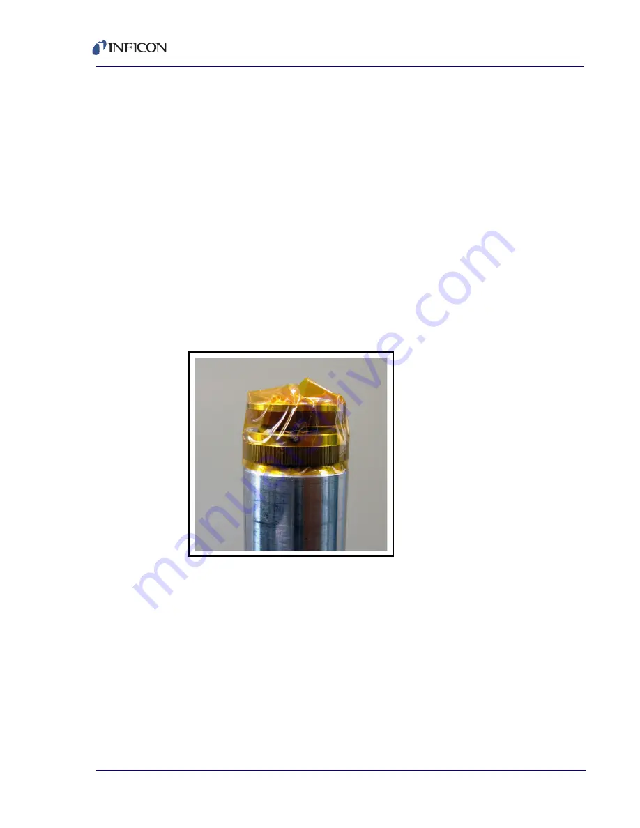
Cut a piece of Kapton® tape (or equivalent), 3.8 cm (1.5 in.) to 5.08 cm (2 in.) 
wide, to a length of approximately 16 cm (6.3 in.).

6

Position the Kapton tape with the bottom edge of the tape on the beveled 
surface just below the knurled ring. Not starting at any of the three bayonet 
pins, wrap the tape around the circumference of the sensor. Fold the excess 
tape over the top of the crystal holder. See 

Figure 2-5

.

Figure 2-5  Wrap Kapton tape

Summary of Contents for RSH-600

Page 1: ...O P E R A T I N G M A N U A L RSH 600 Rotary Sensor Head PN 153800 L Cover Page ...

Page 2: ...ademarks of their respective companies Disclaimer The information contained in this manual is believed to be accurate and reliable However INFICON assumes no responsibility for its use and shall not be liable for any special incidental or consequential damages related to the use of this product Due to our continuing program of product improvements specifications are subject to change without notic...

Page 3: ...Verification 2 3 2 3 Crystal Sensor Installation 2 4 2 4 Mounting 2 5 2 5 Adjustable Flange Installation 2 6 2 6 Copper Head Installation 2 8 2 7 Cooling System 2 8 2 8 Air Supply 2 8 2 9 Crystal Position Feedback Connections 2 9 2 10 Protection from Evaporant 2 9 Chapter 3 Troubleshooting and Maintenance 3 1 Troubleshooting 3 1 3 2 Troubleshooting RSH 600 3 1 3 3 Maintain the Temperature of the C...

Page 4: ... material the deposition controller may be programmed to switch crystals for the next material Switching crystals may also be actuated manually The RSH 600 sensor holds six crystals in a thermally shielded water cooled housing insuring excellent crystal performance in temperature environments up to 300ºC Crystals are housed in an easily removable Teflon and stainless steel crystal holder Crystal p...

Page 5: ...rmation is available under Support at www inficon com where you can contact a Technical Support Engineer with questions regarding applications a Service Engineer with questions regarding troubleshooting diagnosing or repairing a defective sensor Sales and Customer Service to find the INFICON Sales office nearest to you Repair Service to find the INFICON Service Center nearest to you If you are exp...

Page 6: ...ials DOC forms must be approved by INFICON before an RMA number is issued INFICON may require that the sensor be sent to a designated decontamination facility not to the factory 1 5 Unpacking and Inspection 1 If the RSH 600 sensor has not been removed from its shipping container do so now 2 Carefully examine the RSH 600 sensor for damage that may have occurred during shipping This is especially im...

Page 7: ...anual 1 6 Base Configuration RSH 600 Rotary Sensor Head 15320X XX See Figure 1 2 below for possible configurations Figure 1 2 RSH 600 configurations Crystals 2 boxes 10 total 103200 2 Technical Manual 153800 on 074 5000 G1 CD ...

Page 8: ...7 9 in standard 350 mm 13 8 in 450 mm 17 7 in 540 mm 21 3 in 650 mm 25 6 in Power Requirement 115 V ac 50 mA or 24 V dc 20 mA Crystal Switching Method Air Actuated 55 psi 4 kg cm2 regulated Cooling Method Water cooled 5 L m at 2 kg cm2 28 psi Air and Water Connections 3 6 35 mm 1 4 in quick connects Operating Temperature 300 C max with water cooling and Standard Head Cover 400 C max with water coo...

Page 9: ...y See Figure 1 3 153706 Angled Spring Retainer Assembly See Figure 1 4 153714 Flat Spring Retainer Contact Kit See Figure 1 3 153724 Spring Contact See Figure 1 3 and Figure 1 4 153726 Flat Retainer Screw See Figure 1 3 153709 Angled Retainer Screw See Figure 1 4 153715 Angled Retainer Spacer See Figure 1 4 153717 M3x6 Screw for Flat Crystal Retainer Assembly See Figure 1 3 144 101 M3x12 Screw for...

Page 10: ...Stainless Steel Cover Crystal Holder P N 153708 P N 153710 Spring Contact Retainer Screw Spring Retainer Spring Retainer P N 153726 P N 153709 Copper Cover not shown P N 153731 Contact Kit set of 6 P N 153724 Assembly P N 153706 Crystal Retainer Assembly P N 153204 ...

Page 11: ...ainless Steel Cover Copper Cover not shown Crystal Holder P N 153716 P N 153713 P N 153731 2 Spring Retainer Assembly P N 153714 Crystal Retainer Assembly P N 153204 2 Retainer Screw P N 153715 M3x12 Screw P N 144 224 Spring Contact P N 153726 Retainer Spacer P N 153717 ...

Page 12: ...n of any crystal sensor depends on proper placement compatibility of its construction with its operating environment and connection to proper utilities CAUTION RSH 600 must be clean and grease free when installed in the vacuum chamber The sensor must be handled while wearing clean nylon gloves If parts do become contaminated clean them thoroughly using a suitable solvent to avoid outgassing and ex...

Page 13: ...ead covers are made of stainless steel Copper head covers are available for applications where temperature is a concern see Figure 2 1 All versions of RSH 600 are fixed to their specified lengths but may be adapted to be adjustable in length using the optional adjustable mounting flange see section 1 8 for optional accessory information Figure 2 1 RSH 600 sensor head cover cooling efficiency ...

Page 14: ...he following procedure 1 Connect air pressure 55 psi via 6 35 mm 1 4 in plastic tubing to the air inlet fitting at the base of the solenoid valve marked P 2 Connect RSH 600 as shown in Figure 2 2 or use any convenient method of applying and removing the control voltage RSH 600 will advance when the voltage is applied and latch into position when it is removed The electrical pulse duration should b...

Page 15: ...nsor during the initial soak periods If the crystal is hit with even a minute particle of molten material it may be damaged and stop oscillating Even in cases when it does not completely stop oscillating it may immediately become unstable or shortly after deposition begins instability may occur Plan the installation to ensure that there are no obstructions blocking a direct path between the sensor...

Page 16: ...over loosen the retainer ring nut Push the head cover inward while turning it counterclockwise until it stops 1 16 of a turn Pull the head cover outward To remove the optional copper head cover loosen the Allen head screws that clamp the head to RSH 600 then gently pull the head off of the RSH 600 barrel The vacuum system must be equipped with a 5 08 cm 2 0 in diameter aperture port This port must...

Page 17: ...0 sensor 4 If the crystal holder contains any crystals remove the holder and remove and discard the crystals Reinstall the crystal holder 5 Cut a piece of Kapton tape or equivalent 3 8 cm 1 5 in to 5 08 cm 2 in wide to a length of approximately 16 cm 6 3 in 6 Position the Kapton tape with the bottom edge of the tape on the beveled surface just below the knurled ring Not starting at any of the thre...

Page 18: ...push the flange downward sliding the flange onto the sensor barrel See Figure 2 6 Figure 2 6 Slide flange onto sensor barrel 8 Slide the adjustable flange to the desired position on the sensor barrel and then secure the flange to the barrel by tightening the hex socket head screw on the flange 9 Remove the Kapton tape Use a lint free cloth dampened with reagent grade isopropyl alcohol to clean the...

Page 19: ...en rotate the cover so that the crystal in contact with the spring is centered in the hole in the cover 6 Tighten the Allen screws on the clamping ring The clamping ring should be left attached to the head during crystal changing Only the head cover should be removed so the alignment process will not have to be repeated unless the head is removed from the chamber If no flange was ordered and dimen...

Page 20: ... controller operating manual for programming instruction Figure 2 7 Crystal position connector Figure 2 8 Mating connector male crystal position connector RSH 600 provides a switch closure through connector J2 that can be used to indicate which crystal is active at a given time Switch closure will be affected by crystal positions Figure 2 9 Crystal position feedback diagram crystal 1 is the active...

Page 21: ...hould be found and corrected 3 2 Troubleshooting RSH 600 Table 3 1 General troubleshooting SYMPTOM CAUSE REMEDY Crystal fail signal on front panel of unit will not disappear Damaged crystal Replace crystal Loss of electrical signal Check for electrical continuity at the BNC connector Unit will not advance when crystal switch key is pressed Xtal switch error message displayed Loss of pneumatic supp...

Page 22: ...n material built up on the edge of the crystal carousel aperture plate and touching the crystal partially masking full crystal area Clean the crystal carousel aperture plate Crystal does not oscillate or oscillates intermittently both in vacuum and in air Defective or damaged crystal Replace crystal Existence of electrical short or poor electrical contacts Check for electrical continuity and short...

Page 23: ...tal not seated properly in holder Clean or polish the crystal seating surface on the crystal holder Poor thickness reproducibility Variable source flux distribution Move sensor to a more central location to reliably sample evaporant ensure constant relative pool height of melt avoid tunneling into the melt Sweep dither or position where the electron beam strikes the melt has been changed since the...

Page 24: ...ters 3 4 Use the Optimum Crystal Type Certain materials especially dielectrics may not adhere strongly to the crystal surface and may cause erratic readings For many dielectrics adhesion is improved by using crystals with alloy coated electrodes Gold is preferred for other applications 3 5 Crystal Concerns when Opening the Chamber Thick deposits of some materials such as silicon oxide SiO silicon ...

Page 25: ...ing nut 2b Push the head cover inward while turning it counterclockwise until it stops 1 16 of a turn 2c Pull the head cover outward and remove head cover from the head barrel 3 Remove the copper head cover if installed 3a Loosen the three Allen head screws that attach the head cover to the copper clamping ring Leave clamping ring attached 3b Carefully slide the head off of the barrel of the RSH 6...

Page 26: ...4 1 RSH 600 Operating Manual Chapter 4 Outline Drawings Figure 4 1 Sensor head NOTE Dimensions are shown in millimeters ...

Page 27: ... our continuing program of product improvements specifications are subject to change without notice All trademarks are the property of their respective owners PN 153800 L 2018 INFICON Figure 4 2 Adjustable flange dimensions in inches NOTE Dimensions are shown in inches ...

Reviews: