background image

16

Upgrading the Indy Workstation CPU

3.

Install the new PROM chip.

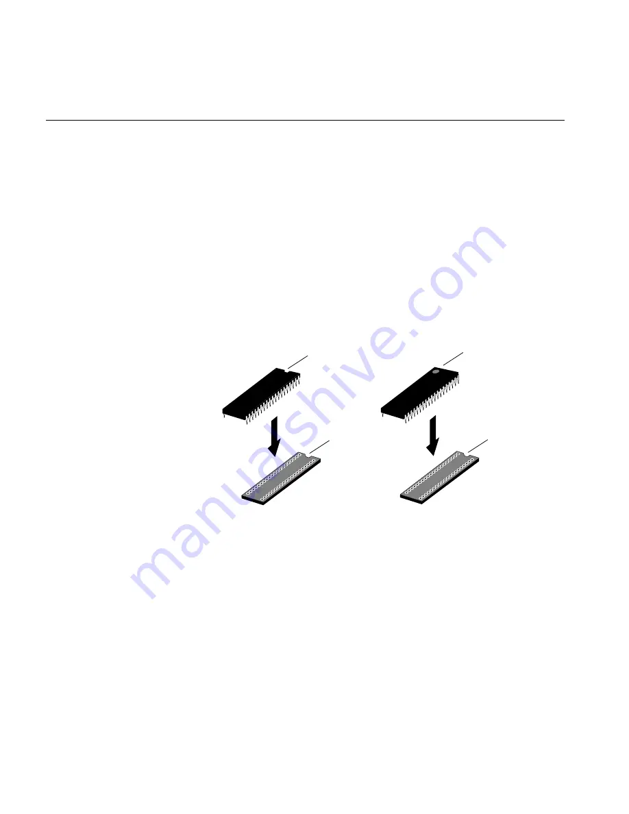
Grasp the new PROM chip. Orient the PROM above the socket on
the system board so the end with the semi-circular notch or small,
indented circle on the PROM chip lines up with the notch in the
socket, as shown in Figure 14.

Caution:

Make sure you line up the notch or the small circle on the

PROM chip with the notch in the socket. If you install the PROM chip
backwards, the system will not power on and you will damage the
PROM chip.

Line up all of the pins on the PROM with the corresponding holes
in the socket.

Figure 14

Lining up the PROM chip

Notch

PROM chip
with notch

PROM chip with
indented circle

Notch

Summary of Contents for R4400SC

Page 1: ...Indy R4600PC 133 MHz and R4400SC 175 MHz CPU Upgrade Installation Guide Document Number 007 9219 003...

Page 2: ...duplicated in any form in whole or in part without the prior written permission of Silicon Graphics Inc RESTRICTED RIGHTS LEGEND Use duplication or disclosure of the technical data contained in this d...

Page 3: ...5 Checking Your System s PROM Version R4600PC 133 MHz Upgrade 6 Replacing the PROM Chip 8 Removing the GIO Option Board 8 Removing the Graphics Board 10 Replacing the PROM Chip 14 Replacing the Graph...

Page 4: ......

Page 5: ...ng the graphics board from the system board 13 Figure 12 Locating the PROM chip on the system board 14 Figure 13 Removing the PROM chip 15 Figure 14 Lining up the PROM chip 16 Figure 15 Pressing the P...

Page 6: ...vi Figure 25 Installing the CPU module 25 Figure 26 Replacing the top cover on the Indy workstation 26 Figure 27 Turning on the Indy workstation 27...

Page 7: ...may not have to replace the PROM See the section Checking Your System s PROM Version R4600PC 133 MHz Upgrade on page 6 Remove and replace the CPU module Replace the cover and restart your system Read...

Page 8: ...lips screwdriver chip removal tool to remove the PROM chip anti static wrist strap Indy R4600PC 133 MHz and R4400SC 150 MHz CPU Upgrade Installation Guide this manual CD not in all upgrades In additio...

Page 9: ...the system Note that it s not necessary to shut down the system software before pressing the power button Figure 1 Turning off the Indy workstation The notifier shown in Figure 2 appears on your scre...

Page 10: ...ide Caution Monitors are very heavy Have someone help you move it 2 Disconnect the following cables from the back of the Indy workstation power cable monitor cable IndyCam cable if connected EtherNet...

Page 11: ...out one inch and tilt it up to remove it Tip It may be difficult to release the cover the first time and you may have to use some force Figure 3 Removing the top cover from the Indy workstation Attach...

Page 12: ...ace the PROM and do not need to check the PROM version first Go to the next section Replacing the PROM Chip on page 8 You check the version of the PROM chip from the Command Monitor while shutting dow...

Page 13: ...the PROM you have At the prompt type version Then press Enter You see a line similar to this PROM Monitor SGI Version 5 0 Rev B6 IP24 Sept 28 1994 BE The date Sept 28 1994 tells you the version of the...

Page 14: ...a double width covers the entire graphics board Figure 6 shows a single width board To determine if your workstation has a GIO option board installed look at your workstation and at Figure 6 If there...

Page 15: ...connect them 3 Using the Phillips screwdriver provided with this upgrade kit remove the two screws from the GIO board connector on the rear of the workstation as shown in Figure 7 Figure 7 Removing th...

Page 16: ...ews to remove Figure 8 Removing the screws from the GIO option board 5 Disconnect the GIO board from the graphics board by grasping the GIO board firmly and pulling it up You are finished removing the...

Page 17: ...ch to unscrew the two hexnuts on either side of the graphics board s I O connector on the rear of the workstation as shown in Figure 9 The wrench is provided with this upgrade Figure 9 Removing the sc...

Page 18: ...nded wrench to unscrew the two standoff screws tall hexagonal posts from the graphics board as shown in Figure 10 3 Use a Phillips screwdriver to remove one screw from the graphics board Figure 10 Rem...

Page 19: ...n Figure 11 Grasp the board firmly on the side close to the system disk drive and pull up to disconnect the two connectors under the graphics board from the sockets on the system board Lift the graphi...

Page 20: ...d on the left of the system board as shown in Figure 12 Figure 12 Locating the PROM chip on the system board Before removing the PROM chip familiarize yourself with it Note that it has either a semi c...

Page 21: ...f and not under the socket You received a chip removal tool it looks like a pair of huge tweezers Insert the chip removal tool between the PROM chip and the socket on the board as shown in Figure 13 W...

Page 22: ...ith the notch in the socket as shown in Figure 14 Caution Make sure you line up the notch or the small circle on the PROM chip with the notch in the socket If you install the PROM chip backwards the s...

Page 23: ...ted in the socket as shown in Figure 15 Figure 15 Pressing the PROM chip into the socket 5 Visually check to make sure all the pins on the PROM are inserted correctly in the holes on the socket and th...

Page 24: ...gonal posts on the system board 3 Connect the graphics board to the system board as shown in Figure 16 Seat the connectors under the graphics board over the sockets on the system board Make sure they...

Page 25: ...the screws on the graphics board s I O connector 5 Insert the two standoff screws that you removed earlier on the graphics board as shown in Figure 18 Use the open ended wrench to tighten them As you...

Page 26: ...n slot on the rear of the workstation as shown in Figure 19 Align the three screw holes on the GIO option board over the vacant standoffs tall hexagonal posts on the graphics board Seat the connector...

Page 27: ...all the way or one of the screws may be screwed down too tightly Look under the board to make sure the connector or connectors are seated evenly and are inserted all the way into the sockets Press the...

Page 28: ...IO option board to the graphics board as shown in Figure 21 As you tighten the screws alternate among them so that the board is connected evenly Figure 21 Installing a single width GIO option board 4...

Page 29: ...is elevated on the system board and is located at the front of the system between the power supply and the system disk drive It is protected by a textured heat sink Do not remove the heat sink Note T...

Page 30: ...d as shown in Figure 23 Figure 23 Removing the two screws from the CPU module 3 Lift the board by bracing your hands against the power supply and the chassis and pushing the board up with your thumbs...

Page 31: ...e connector on the system board Make sure it is positioned correctly before going on to the next step Press down firmly on the CPU module until it is securely seated in the socket on the system board...

Page 32: ...ssis 3 Slide the cover toward the back of the chassis until it snaps into place Figure 26 Replacing the top cover on the Indy workstation 4 If you received a system label in this package place the lab...

Page 33: ...cator LED on the front of the machine is amber for a few seconds and then the LED turns to green and you hear the boot tune If you do not hear the boot tune or the LED is red and does not turn green e...

Page 34: ...am from either Silicon Graphics Inc or a vendor who supplies software Whenever you encounter any problems that you cannot solve using the methods in this booklet contact the organization from which yo...

Page 35: ......

Page 36: ...s to Reach Us The postcard opposite this page has space for your comments Write your comments on the postage paid card for your country then detach and mail it If your country is not listed either use...

Reviews: