


Ref. IS.MDUINO.XXX
*IMPORTANT: I2.5 & I2.6 are not pull-up inputs although they are referred to the I2C pins
(switch configuration). There is a “reverse pull-up circuit “that is stablished in order to have the
same behaviour as the other inputs.
9.2
Serial 0 – RX0/TX0
The Serial0 protocol can work also as a 5V pin. These pins should be used ultimately, only in
case that all the 5V pins are already performing a function. This is because they are shared
with the USB interface. If using these pins, the USB communication cannot be working at the
same time. When the PLC is not installed, the USB communication is normally required for
debugging, uploading and intercommunicating with the Ethernet controller. If using both
interfaces at
the
same time the Arduino board will get blocked.
These pins are not stablished with a pull-up or a pull-down configuration. The state of these
pins is unknown. If these pins must be used, they require a pull-up or a pull-down
configuration. The Arduino board allows the pins to be set in a pull-up configuration. If not it
must be stablished an external pull-up or pull-down circuit in order to correctly work with
these pins.
9.3
Serial 1 – RX1/TX1
These pins are only referred to the inputs I1.5/I1.6. If the switch configuration is in OFF
position the pins RX1/TX1 will be available. If not using the Serial 1 interface these pins can
work as digital, either input or output.
These pins are not stablished with a pull-up or a pull-down configuration. The state of these
pins is unknown. If these pins must be used, they require a pull-up or a pull-down
configuration. The Arduino board allows the pins to be set in a pull-up configuration. If not it
must be stablished an external pull-up or pull-down circuit in order to correctly work with
these pins.
9.4
SPI – MISO/MOSI/SCK
These pins can only work as a 5V pins if the Ethernet protocol is not going to be used. As the
Ethernet protocol uses the SPI to communicate with the Arduino board, both behaviours
cannot happen at the same time as the Ethernet would not work.
These pins are not stablished with a pull-up or a pull-down configuration. The state of these
pins is unknown. If these pins must be used, they require a pull-up or a pull-down
configuration. The Arduino board allows the pins to be set in a pull-up configuration. If not it
must be stablished an external pull-up or pull-down circuit in order to correctly work with
these pins.
Summary of Contents for M-DUINO PLUS series
Page 1: ...Ref IS MDUINO XXX M DUINO PLUS FAMILY M Duino PLUS Family User Guide ...
Page 2: ...Ref IS MDUINO XXX ...
Page 3: ...Ref IS MDUINO XXX Ethernet PLC User Guide Revised March 2018 ...
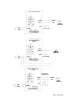
Page 39: ...Ref IS MDUINO XXX Analog Out Turn On Analog Out Turn Off Analog Digital input Turn on ...
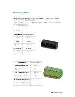
Page 40: ...Ref IS MDUINO XXX Typical Connections ...
Page 41: ...Ref IS MDUINO XXX ...
Page 42: ...Ref IS MDUINO XXX ...
Page 43: ...Ref IS MDUINO XXX ...
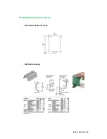
Page 45: ...Ref IS MDUINO XXX Mechanical Characteristics Dimension M duino Family DIN Rail mounting ...


