


Ref. IS.MDUINO.XXX
4. Pin 3/I0.6: Choosing between Pin 3 or the input I0.6. If this switch is ON, it enables the I0.6
input and disables the Pin 3. If this switch is OFF, it enables Pin 3 and disables I0.6. If it is a
Relay Shield I0.6 is changed for I0.1
3. Pin 2/I0.5: Choosing between Pin 2 or the input I0.5. If this switch is ON, it enables the I0.5
input and disables the Pin 2. If this switch is OFF, it enables Pin 2 and disables I0.5. If it is a
Relay Shield I0.5 is changed for I0.0
2. D53(SD): If this Switch is OFF, it enables the Chip Select of the microSD socket and disables
Q2.0. If this switch is ON, it enables the Q2.0 output. If the switch is in ON mode the microSD
can’t be used.
*If the D Zone is an Analog Shield, Q2.0 is also related with D53. Being D53 in ON Mode the SD card MUST NOT be
used because it can corrupt the microSD.
*If the D Zone is a Relay Shield there is no problem and it can be set always to OFF. Q2.0 of the Relay Shield is
related with D12, so it doesn’t affect in any case to the microSD. The pin53 is not connected at all to any
input/output, it is only connected to the uSD chip select.
1. FD RS-485 HD: Choosing between FD or HF. If this switch is ON, it enables the Half Duplex
(HD) option and disables the FD. If this switch is OFF, it enables Full Duplex (FD) and disables
HD.
1.
RTC SDA: This switch enables the communication to communicate with the RTC using
I2C. Having this switch in ON mode it actives this communication, whereas if it is in
OFF mode it disables the I2C to reach the RTC.
2.
RTC SCL: This switch enables the communication to communicate with the RTC using
I2C. Having this switch in ON mode it actives this communication, whereas if it is in
OFF mode it disables the I2C to reach the RTC.
3.
NC: Not connected. This switch is not connected to anything, it doesn’t matter if it is in
ON mode or OFF mode.
4.
NC: Not connected. This switch is not connected to anything, it doesn’t matter if it is in
ON mode or OFF mode.
LEFT ZONE
SWITCH
ON
OFF
NC
-
-
NC
-
-
RTC SCL
RTC
-
RTC SDA
RTC
-
Summary of Contents for M-DUINO PLUS series
Page 1: ...Ref IS MDUINO XXX M DUINO PLUS FAMILY M Duino PLUS Family User Guide ...
Page 2: ...Ref IS MDUINO XXX ...
Page 3: ...Ref IS MDUINO XXX Ethernet PLC User Guide Revised March 2018 ...
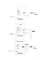
Page 39: ...Ref IS MDUINO XXX Analog Out Turn On Analog Out Turn Off Analog Digital input Turn on ...
Page 40: ...Ref IS MDUINO XXX Typical Connections ...
Page 41: ...Ref IS MDUINO XXX ...
Page 42: ...Ref IS MDUINO XXX ...
Page 43: ...Ref IS MDUINO XXX ...
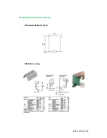
Page 45: ...Ref IS MDUINO XXX Mechanical Characteristics Dimension M duino Family DIN Rail mounting ...


