background image


30 

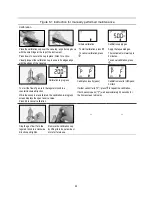
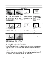
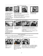
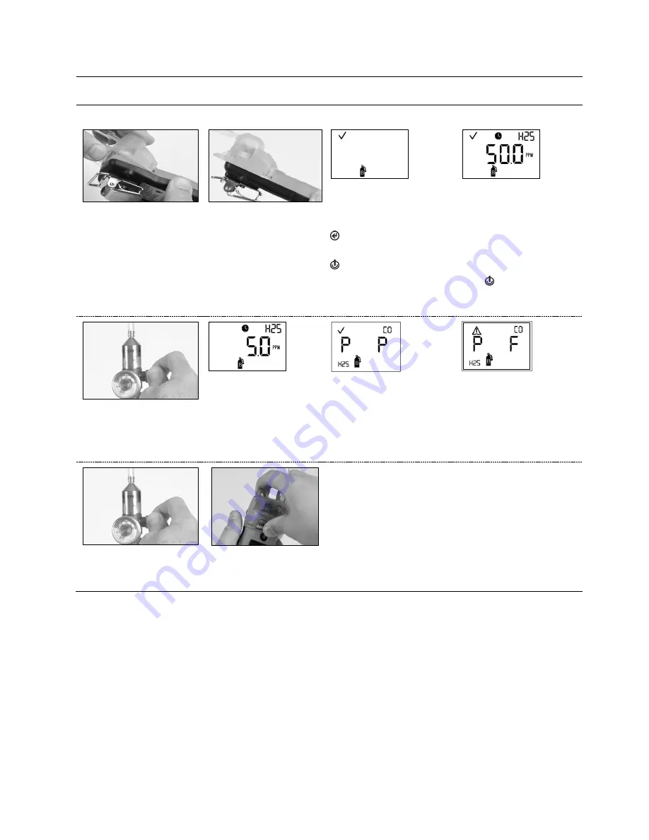
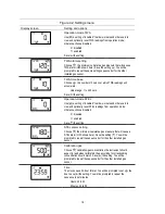
Figure 6.1 Instruction for manually performed maintenance 

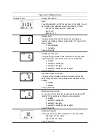
Bump testing 


Initiate bump test  


Bump test apply gas  
 

Place the calibration cup over the case top; align its top 
groove with the small ridge at the top of the instrument.  
Press down to secure the cup in place; listen for a click.   
Visually inspect the calibration cup to ensure its edges align 
with the edges of the case top.    

To start bump testing, press 

.  

To cancel bump testing, press 

.  

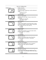
Apply the requested gas.  
The instrument will wait up to 
5 minutes.     
To cancel bump testing, 
press  .  


Bump test in progress 


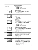
Bump test results (pass) 


Bump test results (pass and 
fail) 

To start the flow of gas, turn the regulator knob in a 
counterclockwise direction.  

If either sensor fail

s (“F”)

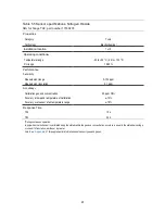
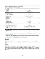
 bump testing, the instrument will 

request calibration.  
If both sensors pass 

(“P”) 

bump testing, the home screen will 

display.   


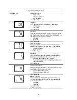
Stop the gas flow!

 Turn the 

regulator knob in a clockwise 
direction and tighten. 

Remove the calibration cup 

by lifting its tabs; set aside 
or store for future use. 


Cleaning the Instrument Exterior 

When cleaning the instrument exterior, do not use alcohol, disinfectants, or solvents, or any substance that 
contains these ingredients as they can damage the gas sensors and otherwise compromise instrument 
integrity.   
For typical dirt and grime, wipe down the instrument with a clean, damp cloth; as needed, use a soap and 
water solution of 8 to 10 parts water to 1-part dish soap, like Dawn®. To achieve a more serious cleaning, 
wipe down the instrument with a bleach and water solution of approximately 50 parts water to 1 part bleach 
as recommended by the US Centers for Disease Control and Prevention (CDC).  
 

Summary of Contents for TANGO TX2

Page 1: ...Product Manual The Essential Guide for Safety Teams and Workers Edition 3 April 30 2021 Part Number 17160218 1...

Page 2: ...ndustrial Scientific Corporation Pittsburgh PA USA Industrial Scientific Co Ltd Shanghai China 2021 Industrial Scientific Corporation All rights reserved Published 2021 Revision 2 www indsci com tango...

Page 3: ...nt 8 Maintenance Recommendations 8 Features and Settings 11 Overview 11 Settings Topics 11 Administrative features 12 Gas alarm features 12 Worker access features 13 Maintenance features 13 Settings m...

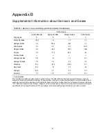
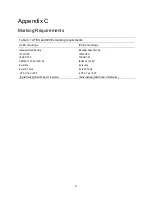
Page 4: ...Liability 38 Appendix A 39 Maintenance Definitions 39 Bump Test or functional test 39 Zero 39 Calibration 39 Appendix B 40 Supplemental Information about Sensors and Gases 40 Appendix C 41 Marking Req...

Page 5: ...ttings 13 Table 4 4 Maintenance features and related settings 13 Figure 4 1 Settings display screen sample 14 Figure 4 2 Settings menu 14 Table 5 1 Instrument specifications 21 Table 5 2 Sensor specif...

Page 6: ......

Page 7: ...ate is DEMKO 12 ATEX 1209126 with marking code Ex ia I Ma and Ex ia IIC T4 Ga for equipment group and category II 1G and I M1 aThe TANGO TX2 complies with relevant provisions of European ATEX directiv...

Page 8: ...r intrinsic safety and may cause an unsafe condition Do not replace battery in hazardous locations Only certified for use with one 1 Tadiran TL 5955 battery cell Sensor openings and water barriers mus...

Page 9: ...noxide with low Hydrogen cross sensitivity CO H2 Low 17160208 specifications Hydrogen Sulfide H2S 17160207 specifications Nitrogen Dioxide NO2 17160205 specifications Sulfur Dioxide SO2 17160206 speci...

Page 10: ...how the instrument when not in alarm will display gas readings As noted in the setting Gas reading display the options are Display readings only for sensor 1 Display readings only for sensor 2 Alterna...

Page 11: ...e followed by a series of display screens which based on settings can include any of the following Visual test screen Version information Calibration date information Calibration gas settings Gas aler...

Page 12: ...TWA reading which also resets its time interval View STEL readings optionally clear a STEL reading which also resets its time interval Alarms Warnings and Notifications Different events can produce t...

Page 13: ...tery System error 888 a Sensor failure Low alarm events and TWA Low alarm gas TWA aVariations 483 for sensor error 408 for no sensor installed Warnings Warnings notify the worker of a condition that n...

Page 14: ...latory standards Use them in combination with company safety policy applicable directives and recommendations of regulatory groups environmental conditions operating conditions instrument use patterns...

Page 15: ...to always on the instrument will perform a self test every 24 hours The self test can be completed on demand by the worker Note The use of calibration gases not provided by Industrial Scientific may...

Page 16: ......

Page 17: ...able of regulations laws and guidelines for their effects on setting choices IMPORTANT Settings that can be adjusted manually through the instrument are described in this chapter these and other setti...

Page 18: ...ntration readings that will cause gas alerts warnings and alarms Optionally use features to latch instrument alarms and set functionality for TWA and STEL Table 4 2 Gas alarm features and related sett...

Page 19: ...ker access is separately set for each task bump test zero or calibration Operation mode bump test Operation mode zero Operation mode calibration Set the display style for calibration date information...

Page 20: ...ss the power button When you want to change a setting use the buttons as follows Press until the desired setting option displays Press to save the setting IMPORTANT When you set something to disabled...

Page 21: ...or s measurement range lower than sensor s low alarm gas setting TWA and STEL multi option Choose the option to enable or disable each feature A disabled feature will not be functional 0 Both TWA and...

Page 22: ...setting of enabled to allow workers and other users to view and optionally reset STEL readings from operation mode otherwise choose disabled 0 disabled 1 enabled Save the setting STEL alarm setting Ch...

Page 23: ...ry 90 seconds otherwise choose disabled 0 disabled 1 enabled for audible chirp 2 enabled for blue lights 3 enabled for audible chirp and blue lights Save the setting Operation mode bump test Use a set...

Page 24: ...m the worker presses 0 disabled 1 enabled Save the setting Vibration alarm Use a setting of enabled if you want the instrument to vibrate during alarms otherwise choose disabled 0 disabled 1 enabled S...

Page 25: ...abled for audible chirp and blue lights Save the setting Maintenance warning interval minutes Set the interval at which the worker will be warned of maintenance due bump test calibration and dock due...

Page 26: ...allow in alarm shutdown 0 prevent shutdown 1 allow shutdown Save the setting Deadband Use this setting to display a gas reading of 0 zero when the detected gas concentration falls within a sensor s d...

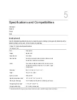
Page 27: ...r mold Case bottom conductive polycarbonate Alarms Three strobe emitting visual alarm LEDs two red one blue 100 dB alarm audible at a distance of 10 cm 3 94 typical Vibration alarm Dimensions 99 x 51...

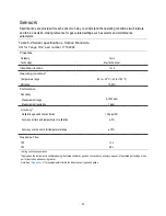
Page 28: ...Temperature range 40 to 50 C 40 to 122 F RH range 15 95 Performance Sensitivity Measurement range 0 1000 ppm Measurement resolution 1 ppm Accuracyb Calibration gas and concentration 100 ppm CO Accura...

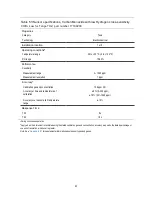
Page 29: ...000 ppm Measurement resolution 1 ppm Accuracyb Calibration gas and concentration 100 ppm CO Accuracy at time and temperature of calibration 5 0 300 ppm 15 301 1000 ppm Accuracy over sensor s full temp...

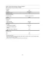
Page 30: ...easurement resolution 0 1 ppm Accuracyb Calibration gas and concentration 25 ppm H2S Accuracy at time and temperature of calibration 5 Accuracy over sensor s full temperature range 15 Response Time T5...

Page 31: ...asurement resolution 0 1 ppm Accuracyb Calibration gas and concentration 25 ppm NO2 Accuracy at time and temperature of calibration 10 Accuracy over sensor s full temperature range 15 Response Time T5...

Page 32: ...e Time T50 20 s T90 80 s aDuring continuous operation bApply when the instrument is calibrated using the stated calibration gas and concentration accuracy is equal to the stated percentage or one unit...

Page 33: ...rs and their calibration gas settings The instrument may be set for the quick or standard process type for calibration and bump testing The quick process permits only one application of gas This setti...

Page 34: ...of the calibration tubing to the regulator s nipple Connect the other end of the tubing to the calibration cup Proceed with the instruction set below for the desired task Zero and calibration Zero In...

Page 35: ...e instrument will wait up to 5 minutes To cancel calibration press Calibration in progress Calibration results pass Calibration results H2S pass CO fail To start the flow of gas turn the regulator kno...

Page 36: ...F bump testing the instrument will request calibration If both sensors pass P bump testing the home screen will display Stop the gas flow Turn the regulator knob in a clockwise direction and tighten...

Page 37: ...e any attempt to remove or reposition the item may cause it damage Use care when working with gas sensors and the case top s water barriers Do not touch the membranes as this can contaminate these ite...

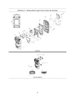
Page 38: ...32 Illustration 7 1 Disassembled Tango TX2 and case top assembly Instrument Case top assembly...

Page 39: ...7160204 Includes sensor and polycarbonate plate Hydrogen Sulfide H2S Yes 17160207 Includes sensor and polycarbonate plate Nitrogen Dioxide NO2 Yes 17160205 Includes sensor and polycarbonate plate Sulf...

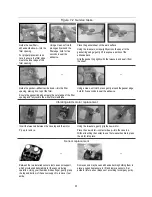
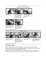
Page 40: ...barrier s edge gently lift to expose a portion of its adhesive back Peel the barrier from the sheet Guide the new barrier adhesive side down onto the case top positioning it over the speaker Place you...

Page 41: ...f the filter opening and fully covers the white filter membrane Using a clean soft cloth press gently around the gasket edge hold for five seconds to seal the adhesive Vibrating alarm motor replacemen...

Page 42: ...ecure sensor by applying gentle pressure to the sides of the sensor case Do not touch the sensor s membrane You will feel a slight connection impact when the sensor is secured in place Aligning its wi...

Page 43: ...case bottom Use a straight down motion to guide the sensors into the sensor barrels Press to secure the case top and case bottom Using a torx screwdriver insert and tighten each of the four screws int...

Page 44: ...ver except liability from personal injury caused by Industrial Scientific s negligence whether arising under contract warranty tort including negligence strict liability products liability or any othe...

Page 45: ...linder or ambient air that is known to be clean air If there are gases in the air sample that are below the lowest alarm level the instrument will read them as zero its only task is to read the air sa...

Page 46: ...ydrogen 24 0 0 1 0 0 1 0 Ammonia 1 0 0 0 0 0 0 0 No data available Note This table is provided as a guide only and is subject to change The data reflect the percentage response of the sensor type when...

Page 47: ...markings Industrial Scientific Corp 15205 USA TANGO TX2 DEMKO 12 ATEX 1209126 Ex ia I Ma Ex ia IIC T4 Ga 40oC Ta 50oC Serial Number Month Year of Production Industrial Scientific Corp 15205 USA TANGO...

Page 48: ...515 To locate a nearby distributor of our products or an Industrial Scientific service center or business office visit us at www indsci com Rendez vous sur notre site Web www indsci com si vous voulez...

Reviews: