


Big Buck Hunter™
Page 13
Version 01/05
© Copyright 2004-2005 Incredible Technologies, Inc. All Rights Reserved. Unauthorized duplication is a violation of applicable law.
All other marks are the properties of their respective owners. All rights reserved.
SYNC
This is the recommended approach for a Wells-Gardner
monitor and should work with some others as well.
If your monitor does not have a composite SYNC input but
has separate horizontal and vertical SYNC inputs, try
connecting the composite SYNC signal from the PCB to
the negative horizontal SYNC signal on the monitor. This
should produce a satisfactory result, although some
adjustment of the monitor's SYNC controls may be
necessary.
Coin Doors, Test Switch, and Volume
Control Panel
Wire the coin doors and the test switch(es) as per the
JAMMA Harness Connection table on page 35. Connect
the door lamps to the +12 vdc supply. Some games have
separate power supply outputs for the lamps.
Install a test switch somewhere convenient inside the coin
door area. This switch allows you to enter adjustables, run
diagnostics, and see or clear audits. Make it readily
accessible through the coin door. Wire it to the Test wire
on the JAMMA Harness.
BIG BUCK HUNTER has the ability to adjust volume at
any time during a game. Install two push button switches
(not included) inside the coin door for easy access.
Connect the switches to the JAMMA harness. Refer to the
JAMMA Harness Connection
table on 35.
Final Check
Check the game inside and out for any imperfections.
Secure any loose wiring or fastening hardware.
Make sure the coin door is tight and the coin mechs are
well adjusted.
NOTE:
Make sure all assemblies are firmly attached. Anything that is
not mounted securely will rattle when the game is played.
This game makes use of low-frequency sounds that can
cause any loose joints to rattle.
D
IP
S
WITCH
S
ETTINGS
The
SW51-Dip switches
can be found on the main PCB
near the JAMMA connector.
Dip Switch 1 (ON):
Normal Play (DEFAULT)
Dip switch 1 (OFF):
OPERATOR MODE
Dip switch 2 (ON):
Always "ON" (DEFAULT)
Dip switch 3 (ON):
Always "ON" (DEFAULT)
Dip switch 4 (ON):
Always "ON" (DEFAULT)
The
SW5-Dip switches
can be found near the flashing
green LED. These are used to adjust monitor resolution in
Kits.
Dip switch 1 (OFF): Medium Resolution (DEFAULT)
Dip switch 1 (ON): Low Resolution
**Dip switch 2 (OFF): Low Resolution B Adjust
Dip switch 2 (ON): Low Resolution A (DEFAULT)
Dip switch 3 (ON): Always "ON" (DEFAULT)
Dip switch 4 (ON): Always "ON" (DEFAULT)
**If you are experiencing a “jittery” image, try this mode to
correct. Restart the game and adjust the monitor
Note: Low-resolution works on BBH KITS
ONLY
!
C
ONNECTING THE
P
HONE
L
INE
In order for your game to enjoy online features, you must
connect the game to a regular telephone line. ITNet
requires a regular phone line that gives a dial tone. Phone
systems that are not direct outside lines may not work.
1. Make sure that the supplied long telephone cable is
plugged into the modem connector on the PCB labeled
PHONE 1. Thread the cable through the mouse hole
below the back door.
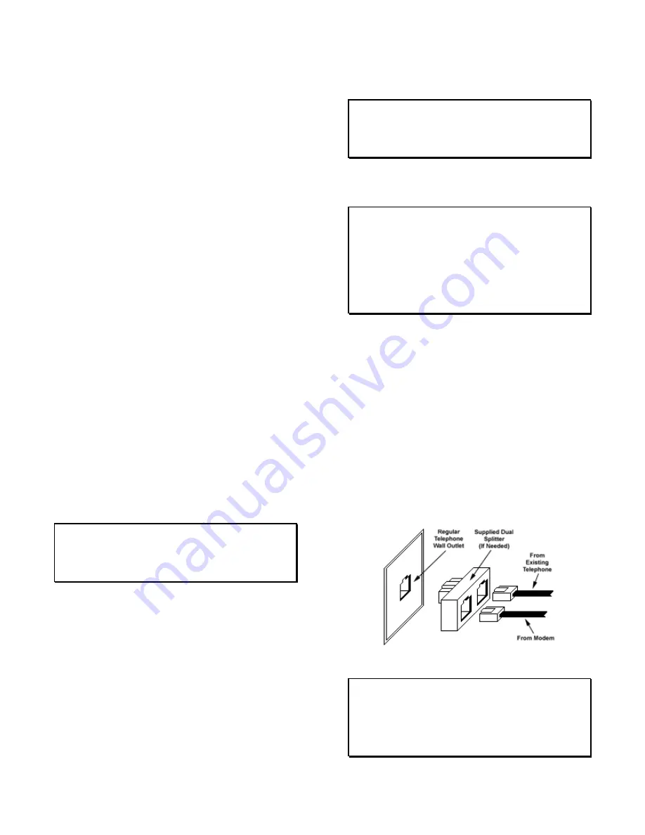
2. Connect the loose end of the long cable into any
existing telephone jack. Use the included splitter if you
are connecting to a jack already in use.
Connecting to the Wall
IMPORTANT!
Your game will receive code updates through the phone line,
even if you are not registered with the ITNet system.
However, you MUST be registered with ITNet and
appropriate operator papers must be on file wi th Incredible
Technologies, Inc. or your game will not receive the ITNet
play features.


