


5
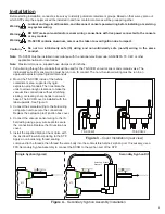
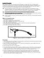
6. Plumb the siphon hose from the VAC port of the TS-SCCM to the siphon check valve. Secure the hose to the fittings
using one of the supplied hose clamps at each end.
7. Plumb the containment vacuum hose from the INT port of the TS-SCCM to the containment area to be monitored.
Secure the hose to the fitting using one of the supplied hose clamps per fitting. Install T-fittings and clamps where
necessary to connect the hoses if more than one containment area will be monitored as a group.
Note:
The containment vacuum hose must be placed in the lowest point of the containment space. For double walled
tanks, this means ensuring that the vacuum line rests at the bottom most part of the tanks interstitial space. Use
the same industry procedures used to install any sensor at the bottom of a double walled tank.
8. Secure all containment boots, lids and caps. Clean pipe surfaces to clear debris or foreign objects prior to tightening
secondary test boots on secondary containment product or vapor return piping. Make all jumper connections inside of
dispenser sumps by using supplied hardware.
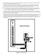
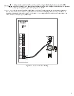
9. Inside the console, the TS-SCCM solenoid wiring must enter the console from the explosion proof rigid conduit through
a designated knockout on the non-IS side of the barrier inside. Connect the line, neutral, and ground wire of the
solenoid to a single unused channel on the Relay Module (RLY). The solenoid should be wired to the Common (C) and
Normally Open (NO) contacts of the channel selected. Source voltage (110 VAC) will need to be provided to the dry
contact relay.
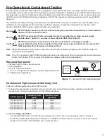
Earth Ground
Figure 5
–
Solenoid Wiring
Summary of Contents for TS-5000
Page 27: ......
Page 28: ... 2013 FFS 000 0528 Rev E ...


