


Sigma_CP_Australian Interface Module.doc
Page 6 of 9
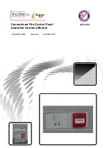
Figure 2-Power connection
5
24V Input
The Australian Interface Module requires a nominal
24V DC power supply to operate. This can be taken
from the AUX 24V output of the panel to which the
ancillary board is connected or another 24V DC source
if this is more convenient.
Four power terminals are provided so that 24V DC
wiring can be taken into the module and then out again
on to other ancillary boards or other equipment.
6
Connection to main panel and other boards
If power is supplied locally to the Australian Interface Module board only two wires are required
from the main panel.
Wiring can be standard fire alarm cable or shielded data cable. The shield of the cable must be
securely bonded to the enclosure case at both ends, and must comply with the relevant Australian
Standards.


