
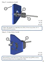
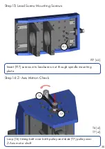
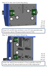
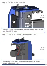


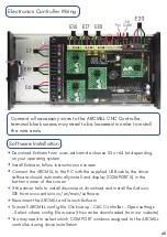
Step 15: X-Axis Limit Switch Mounting
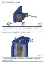
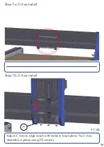
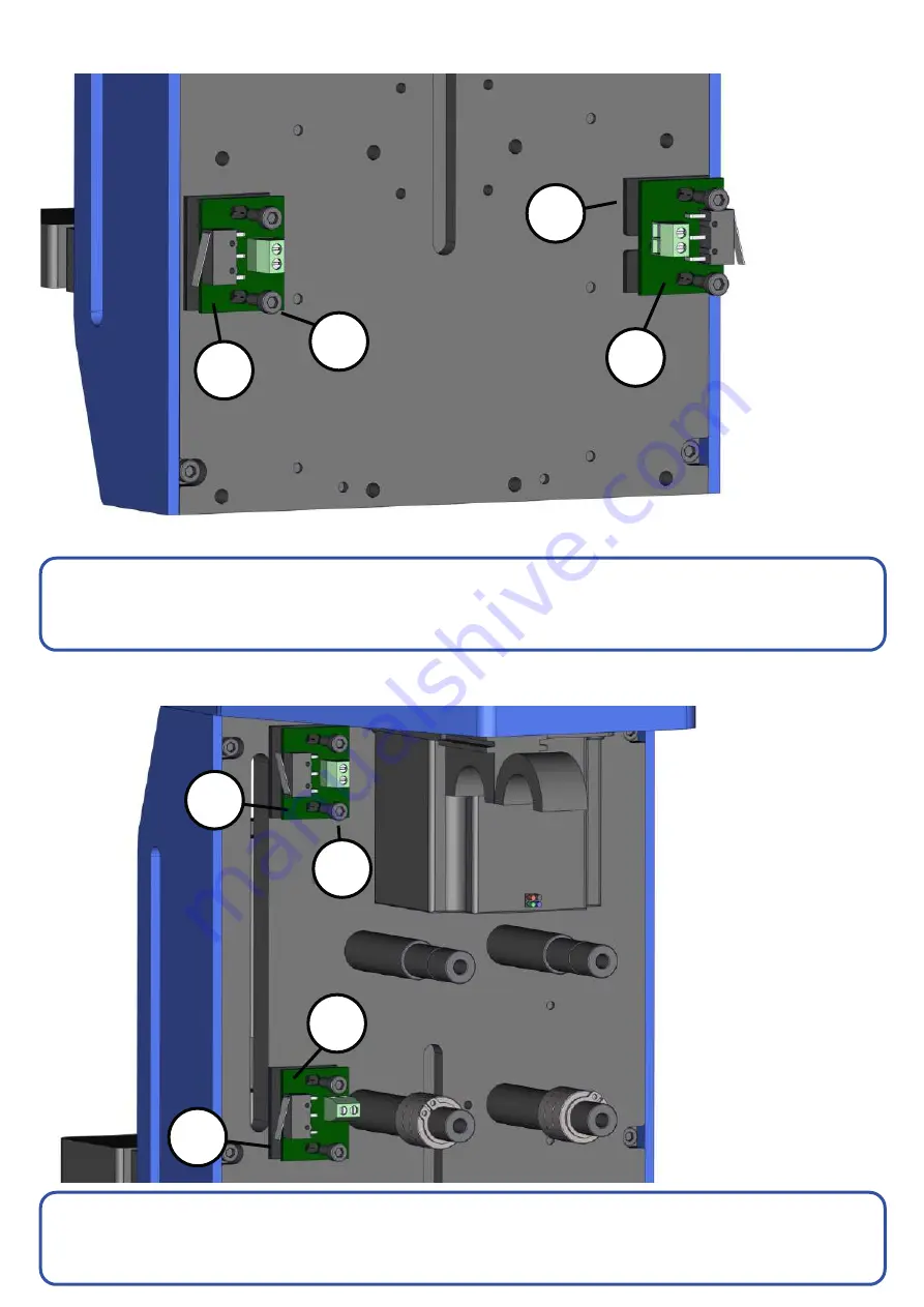
Step 16: Z-Axis Limit Switch Mounting
Mount (E1 and E2) limit switches to rear of Z-Axis assembly using
(F4) screws, place (F31) spacer behind switch PCB’s
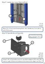
Mount (E2 and E3) limit switches to Z-Axis assembly using (F4)
screws, place (F31) spacer behind switch PCB’s (Adjustment)
F31
F31 (x2)
E2
F4
E2
F4
E1
F4 (x4)
E2 (x1)
E1 (x1)
F31
E3
F31 (x2)
F4 (x4)
E3 (x1)
E2 (x1)
31
Summary of Contents for ARCMILL
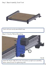
Page 1: ...Assembly Instruction Guide 03 06 2019 Version 1 3 ...
Page 4: ...Base Frame Assembly 3 ...
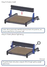
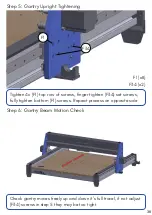
Page 14: ...Gantry Upright Assembly 13 ...
Page 18: ...Gantry Beam Assembly 17 ...
Page 23: ...Z Axis Assembly 22 ...
Page 36: ...Complete Assembly 35 ...


