background image

®

Environmental Equipment, Inc.


IMR EX660 User Manual 


3632 Central Ave. St. Petersburg, FL 33711 – Phone: 727-328-2818 / 800-RING-IMR – Fax: 727-328-2826 – E-mail: [email protected] – Web: www.imrusa.com 

THE PRIDE OF THE COMPANY – MADE IN THE USA 


Page 

21

 of 

27


11.


Usage Notice 


Do not drop from highs and avoid severe impacts. 


The instrument may not operate properly in an environment with gas of excessively high concentrations. 


Follow all guide lines in this manual to ensure optimum performance of the device. Failure to do so will 
result in incorrect readings or damage to the device. 


Do not store or operate the device in an environment containing corrosive gas or vapor (for example 
chlorine of high concentration). Do not expose the device to other harsh environments (including excessive 
cold, heat, humidity, electromagnetic field and intense light). 


Use a damp cloth to clean the housing of the device. Do not use caustic chemicals or abrasive materials this 
can cause damage or scuffing to the housing. 


Disassembly of the device and replacement of parts must be performed by a qualified person. 


It is highly recommended to re-calibrate the device once a year. 


Always dispose of used batteries and sensors in accordance with local governmental and regulatory 
standards. 


Do not charge the device or upload data to a PC in a hazardous area. 


For any usage or issue that is not described in this manual contact IMR for advice. 


Summary of Contents for EX660

Page 1: ...ronmental Equipment Inc IMR EX660 Portable SMART Sensor Gas Detector User Manual Read this manual carefully before using this device 727 328 2818 800 RING IMR Fax 727 328 2826 www imrusa com email info imrusa com ...

Page 2: ...ure and Functions 7 5 Operation Instruction 8 5 1 Power On 8 5 2 Power Off 9 5 3 Bump Test 9 5 4 Menu Overview 10 5 4 1 Settings Menu 10 5 4 2 Advanced Menu 11 5 5 Gas Detection 12 5 6 Status Review 12 5 7 Auto Zero Calibration 12 5 8 Calibration 13 5 8 1 Accessing the Settings Menu 13 5 8 2 Zero Calibration 14 5 8 3 Span Calibration 15 5 9 Alarm Point Setting 17 5 10 Channel Setting 18 5 11 Passw...

Page 3: ...tral Ave St Petersburg FL 33711 Phone 727 328 2818 800 RING IMR Fax 727 328 2826 E mail info imrusa com Web www imrusa com THE PRIDE OF THE COMPANY MADE IN THE USA Page 3 of 27 11 Usage Notice 21 12 Appendix1 Gas List 22 12 WARRANTY 23 13 Contact Information 24 ...

Page 4: ...used It s exceedingly hazardous to charge the device in a dangerous environment Do not expose the device to the exceedingly high concentrations of detectible gases for an extended period of time It will harm the performance of and even damage the device If exposed to an environment consisting of leaded compounds sulfide compounds organic phosphorus compounds or silicon the gas sensors will be dama...

Page 5: ...Its functional and watertight design IP 66 incorporates a rugged impact resistant rubberized housing to meet the toughest requirements of harsh environments 2 Main Features Advanced 16 digit MCU with low consumption Ultra wide angle LCM screen with backlighting Adjustable 2 level alarm point Adjustable calibration point Self preservation design for combustible gas sensors Battery low voltage alert...

Page 6: ...er to the Appendix 1 in the end of this manual Response time Semi conductor catalytic thermal conductor sensors T90 30s O2 CO H2S sensors T90 30s Other sensors T90 120s Indication error range Combustible gas 5 F S Toxic gas 5ppm Operating environment Temperature 20 50 Humidity 95 RH Power source Lithium battery DC3 6V 6600mAh Run time per charging 30 hours continuously no alarm Charging time 6 hou...

Page 7: ...anual 3632 Central Ave St Petersburg FL 33711 Phone 727 328 2818 800 RING IMR Fax 727 328 2826 E mail info imrusa com Web www imrusa com THE PRIDE OF THE COMPANY MADE IN THE USA Page 7 of 27 4 Structure and Functions Appearance Display information ...

Page 8: ...IN THE USA Page 8 of 27 5 Operation Instruction 5 1 Power On When the device is powered off hold for at least than 3s and the device will power on The screen below will be shown After power on the detector will begin to self test The screen below will be shown The device will self test the buzzer alarm lights and vibrator automatically After self testing the device enters into normal detection mod...

Page 9: ... screen will show Shutting down Meanwhile the buzzer will give out an intermittent beep twice Then the device will power off 5 3 Bump Test Every day before using the device it is suggested to carry out a Bump test so as to check if the device is working normally Test method When the device is powered on put it into an environment with a high level of gas The test gas should be higher than a preset...

Page 10: ...r into the settings menu Below are the menu items Menu Submenu Remarks DATE TIME When changing the date or time the selected digit will blink ALARM MODE When changing the mode the selected item will blink A filled circle enabled RECORD GAP Record saving interval CAUTION MESSAGE A filled circle enabled BATTERY MESSAGE Displays battery voltage and remaining work time BACKLIGHT TIME Sets backlight ti...

Page 11: ...rd Input the password by pressing to increase the value and press to confirm the input After entering the correct password press to enter into advanced settings menu Select a submenu item by pressing and enter into a selected submenu by pressing Menu Submenu Remarks SAFETY DEPLOY Sets user s ID ZERO CAL Preforms a zero calibration DATA UPLOAD Sets the device in Data upload mode PERIPHE CONFIG One ...

Page 12: ...cessively high concentration of gas may cause zero drift of the gas sensors If the reading in clean air is not zero preform a zero calibration as outlined in Section 6 7 and 6 8 5 6 Status Review In normal detection mode press and the screen will show current temperature time STEL value TWA value the maximum level of gas and the minimum level of gas since power on Note Only for toxic gas Only for ...

Page 13: ... the device is powered off hold both and buttons simultaneously for about 3 seconds Then the device will perform a self test as it powers on After a short delay you will be prompted for a password After inputting the correct password the device enters into the setting menu shown below Press to change the selected icon The currently selected icon will flash Then press to enter the submenu WARNING C...

Page 14: ...Zero Calibration Select icon and press to enter the auto zero calibration screen as shown below When finished a icon show for completed gas sensor s and for failed gas sensor s In the auto zero calibration screen press and the device enters manual zero calibration mode as shown below When the AD value of the sensor is stable press to make zero calibration manually After that a icon show for comple...

Page 15: ... IN THE USA Page 15 of 27 5 8 3 Span Calibration After zero calibration the device displays a countdown interface as shown below After that it displays the calibration gas level as shown below If the level needs to be changed press to enter the below interface Press to move the cursor and press to change the figure After changing the figure press to save and enter the calibration gas input mode as...

Page 16: ...n gas the display will update as below During this period if a change to manual calibration mode needs to be made press Below is the manual calibration interface Press again to confirm manual calibration The below 2 screens show a succeeded and failed manual calibration Once calibration on one sensor is completed the device continues on to calibrate the next sensor one by one The operation is the ...

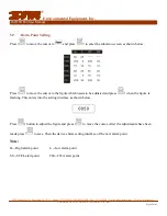
Page 17: ...cursor to and press to enter the submenu screen as shown below Press to move the cursor to the figure which needs to be adjusted and press when the figure is flashing This enters into the setting interface as shown below Press button to adjust the figure and press to move the cursor After the adjustments have been made press to save Then the device enters setting interface of the next alarm point ...

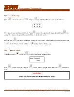
Page 18: ... will flash Press to move the cursor to the target channel Press to change the selection If enabled the center is black if disabled it s white Keep pressing until all the channels have been set The device will save the setting and exit to the normal detection mode Closed channels will have a displayed in the channel box 5 11 Password Setting Move the cursor to and press to enter the submenu as sho...

Page 19: ...e indicator is full all black charging is completed Then disconnect the charger from both power and then the device 7 USB Communications optional The USB data cable and software CD are required to utilize this function For details refer to the software manual 8 Calibration and Replacement of Sensor Modules The device uses smart sensor modules It is suggested to calibrate them every year If a senso...

Page 20: ...ing Problem Possible Causes Solution Won t power on Battery voltage too low Charge it immediately System damaged Contact IMR Circuit fault Contact IMR No response to gas Warm up not completed Wait till it finishes Circuit fault Contact IMR Sensor readings no longer accurate Sensor overdue for calibration Contact IMR Sensor drift Re calibration required Time and date are not correct Battery is empt...

Page 21: ...e in an environment containing corrosive gas or vapor for example chlorine of high concentration Do not expose the device to other harsh environments including excessive cold heat humidity electromagnetic field and intense light Use a damp cloth to clean the housing of the device Do not use caustic chemicals or abrasive materials this can cause damage or scuffing to the housing Disassembly of the ...

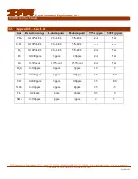
Page 22: ...ndix1 Gas List Gas Detection range L alarm point H alarm point TWA ppm STEL ppm CH4 0 100 LEL 20 LEL 50 LEL N A N A C3H8 0 100 LEL 20 LEL 50 LEL N A N A H2 0 100 LEL 20 LEL 50 LEL N A N A H2 0 1000ppm 35ppm 250ppm N A N A O2 0 30 vol 19 5 vol 23 5 vol N A N A H2S 0 100ppm 10ppm 15ppm 10 15 CO 0 1000ppm 35ppm 200ppm 35 200 CO 0 2000ppm 35ppm 200ppm 35 200 NH3 0 100ppm 25ppm 50ppm 25 35 CL2 0 20ppm ...

Page 23: ...f IMR 5 No warranty claims may be made for maintenance and setting work cleaning or other utility materials required for the function of the unit and other wear parts unless they have a direct bearing on work performed under the warranty 6 The terms and conditions for the acknowledgement of this warranty shall be the presentation of the fully completed warranty card which must contain the confirma...

Page 24: ...rusa com THE PRIDE OF THE COMPANY MADE IN THE USA Page 24 of 27 13 Contact Information Environmental Equipment Inc 3632 Central Ave St Petersburg FL 33711 USA Phone 727 328 2818 Fax 727 328 2826 1800 1 800 746 4467 Internet www imrusa com Email info imrusa com sales imrusa com technical_department imrusa com IMR is a registered Trademark of IMR Environmental Equipment Inc ...

Page 25: ...uipment Inc IMR EX660 User Manual 3632 Central Ave St Petersburg FL 33711 Phone 727 328 2818 800 RING IMR Fax 727 328 2826 E mail info imrusa com Web www imrusa com THE PRIDE OF THE COMPANY MADE IN THE USA Page 25 of 27 ...

Page 26: ...uipment Inc IMR EX660 User Manual 3632 Central Ave St Petersburg FL 33711 Phone 727 328 2818 800 RING IMR Fax 727 328 2826 E mail info imrusa com Web www imrusa com THE PRIDE OF THE COMPANY MADE IN THE USA Page 26 of 27 ...

Page 27: ...uipment Inc IMR EX660 User Manual 3632 Central Ave St Petersburg FL 33711 Phone 727 328 2818 800 RING IMR Fax 727 328 2826 E mail info imrusa com Web www imrusa com THE PRIDE OF THE COMPANY MADE IN THE USA Page 27 of 27 ...

Reviews: