background image

Visit www.improvedracing.com for additional support

12

6. 

Use an angle finder to match the 4° tilt of the factory radiator stack and 

hold this position to trace the hole for the lower bracket.

 Tip:

 When on wheel ramps, re-measure the angle on your ramps.

7.  Use a permanent marker to trace the hole outline for drilling.
8.  Remove the cooler and bracket assembly from the car.
9.  Strike the hole center with a punch and use a sharp #1 (.2280 inch) drill 

bit to create the hole in the bumper bar for the bottom oil cooler bracket.

10. 

Re-mount the cooler and bracket assembly back onto the car by first 

securing the top bracket with a 12 mm tool and two HSC-1041 screws. 
Torque the M8 screws to 24 lb-ft (33 N-m).

11.  Attach the bottom bracket to the bumper bar using a drill, 

3

/

8

 inch socket 

and HSC-1054 thread cutting screw. DO NOT over-tighten.

 Tip:

 Use aligned, firm pressure with a drill set to low speed (Speed 1).

12.  Grab the oil lines and route them towards the back of the car as shown 

in Figure 13.

 Tip:

 E5G-600-50 is biased towards the passenger side of the car.

 Tip: 

E5G-600-51 is biased towards the driver side of the car.

E5G-600-50

E5G-600-51

Figure 13 - Routing the Oil Lines Rearwards

Summary of Contents for E5G-600

Page 1: ...cing com Copyright 2008 2019 Improved Racing Products LLC All rights reserved Rev 190528 OIL COOLER KIT FOR 2010 2011 CHEVROLET CAMARO V8 PART NUMBER E5G 600 MADE IN USA Important Read these instructi...

Page 2: ...0 IN Adapter 90 OUT Exchanger 6 1 E5G 600 51 Line 0 OUT Adapter 45 IN Exchanger 7 1 E5G 600 60 Upper Bracket Hardware for Mounting MHX 245 8 1 E5G 600 61 Lower Bracket Hardware for Mounting MHX 245 9...

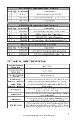
Page 3: ...ICAL SPECIFICATIONS Maximum Operating Temperature 302 F 150 C Minimum Operating Temperature 22 F 30 C Maximum Operating Pressure 300 psi 20 68 bar Heat Exchanger Material Fabrication 45 Row Full Alumi...

Page 4: ...w WARNINGS PRECAUTIONARY STATEMENTS WARNING NEVER work under a vehicle supported only by a jack WARNING DO NOT CAP OFF THE OIL COOLER PORTS after the adapterisinstalled Runningtheenginewiththeportscap...

Page 5: ...screws at each corner under the hood circled in red on Figure 1 6 Underneath the car use a 10 mm tool to remove the two screws which hold the bumper cover to the chassis circled in green on Figure 2...

Page 6: ...xtended10mmsocketwrenchtoremovefourscrewssecur ing the bumper cover to the fender support c Unplug all fog light harnesses 10 With two people carefully pull the bumper cover straight off the front Tip...

Page 7: ...factory oil cooler and pop off the black plastic protectors shown in Figure 7 to gain access to the clover shaped wire clips that secure the factory lines into the fittings Tip There are two caps on t...

Page 8: ...se circuit that feeds the factory oil cooler d Locate the tee junction on the upper radiator hose e Follow the small line back to the lowest hose clamp and remove the 2 hose clamp using channel lock p...

Page 9: ...coolant plug to 45 lb ft 60 N m followed by a 1 4 turn 14 Use a 13 mm tool to remove the four M8 screws that hold the factory oil cooler to the side of the oil pan 15 Remove the factory oil cooler and...

Page 10: ...T over tighten 18 Pre fill and reinstall a new engine oil filter after lubricating the seal with engine oil 19 Reconnect the spark plug wire for Cylinder 1 20 Reinstall the bumper bar onto the car if...

Page 11: ...a low profile tool should your headers interfere 4 Use E5G 600 60 and E5G 600 61 Hardware Kits to secure the top and bottom brackets to MHX 245 as shown in Figure 11 5 Use a 12 mm tool and two HSC 10...

Page 12: ...r the bottom oil cooler bracket 10 Re mount the cooler and bracket assembly back onto the car by first securing the top bracket with a 12 mm tool and two HSC 1041 screws Torque the M8 screws to 24 lb...

Page 13: ...the hose end to 20 lb ft 27 N m Tip Connect the 90 hose end with heat shield at the adapter side 15 Arrange HSC 1052 HWA 1003 and CP 16 from the E5G 600 62 Hard wareKitasshowninFigure14 thensecurethe...

Page 14: ...ering line 19 Reinsert the screw into the chassis and tighten to no more than 7 lb ft 10 N m 20 Peel backtheblackplasticshroudcircledin greenonFigure17androute the system lines up towards MHX 245 21 U...

Page 15: ...the 90 hose end to the top fitting on the oil cooler Tighten the hose end to 20 lb ft 27 N m Wipe up any oil that spills WASHER BOTTLE FRAME WELDED NUT REAR FRONT DRIVER PASSENGER Figure 18 Securing t...

Page 16: ...lant level and add coolant if necessary Tip Consult the vehicle s factory service manual for the correct inspec tion and filling procedures 6 Start the vehicle and inspect for oil and coolant leaks Be...

Page 17: ...for locations 7 Put the wheels back on if applicable 8 Use a T20 tool to replace all screws underneath the bumper cover im mediately in front of the wheels There are four per side Cite Figure 5 for lo...

Reviews: