Impex LD8000 User Manual Download Page 10

Laser Diode Driver LD8000 

10 

Ver. 1.0 

4.2 The LD Control software 

The LD Control software application gives you the ability to adjust parameters quickly, to view 
values on the screen and to save them to a file for documentation 


Since  the  remote  control  feature  qualifies  to  operate  the  laser  without  intervisibility, 
special considerations and precausions must be met! Do not operate the laser in rooms, 
where no sufficial laser safety is guaranteed! See also the chapter Interlock. 

Installing LD Control (Windows) 

To install LD Control software, run setup.exe from the supplied CD-ROM. This will install the 
application  itself  and  some  additional  runtime  components.  Follow  the  instructions  of  the 
installer software and reboot the computer, if you will be asked to do. 

Installing USB driver (Windows) 

When you first time connect the LD8000 to the PC, the operating system will ask for a driver. 
Select the option 

“Search in other places”

 and point to the folder 

USB Driver\Windows

 on the 

CD-ROM. The device is equipped with a USB-serial converter module, so a connection to it is 
made through a virtual COM Port. The number of the COM Port interface is being assigned by 
the operating system automatically. To find out the corresponding COM Port number, start the 
Device  Manager  (Start  –  Run...  -  devmgmt.msc)  and  look  for  “USB  Serial  Port”  entry  in  the 
Ports section, the assigned COM Port number is shown in parentheses. 

Overview 

Every control and indicator is equipped with online description. Get the mouse pointer over an 
element for view seconds and the description will pop up. 
 
The application is divided into five parts, represented by a card index. On the 

System

 card you 

can  setup  the  communication  interface  and  some  basic  parameters.  On 

Current 

and 

Temperature 

cards  you  can  set  all  adjustable  values  to  run  the  laser  properly.  The  PID 

parameters  of  the  temperature  controllers  can  be  tuned  on  the 

PID  controllers

  card.  The 

Monitor

 card shows and logs actual values such as laser diode current and temperatures. 


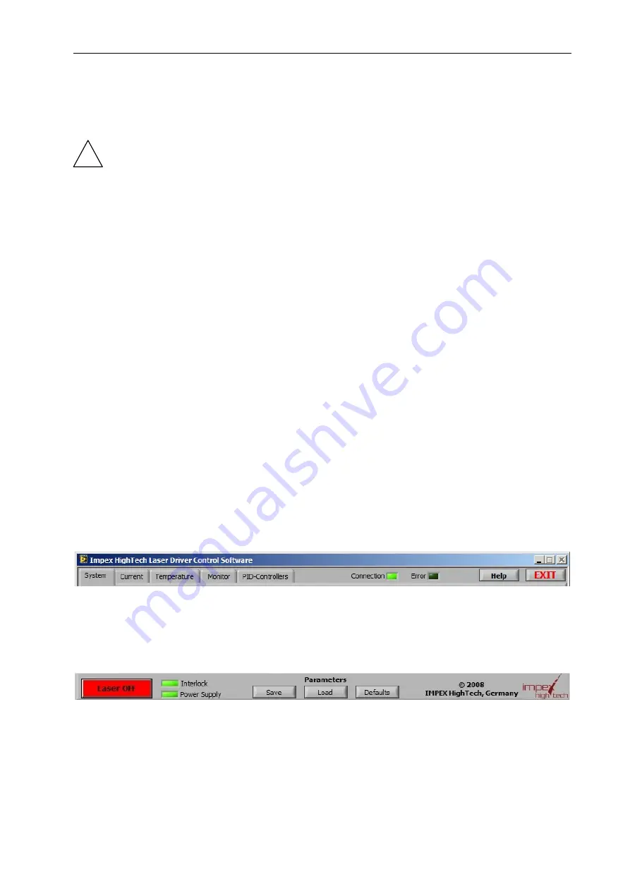
Right to the card tabs there are indicators for 

Connection

 and eventually occured 

Error

. When a  

connection to the device is not established (the Error indicator is lit and the Connection indicator 
is dim), then the other indicators and parameters are not valid and are greyed out. See description 
of the System card in such case. 
Further there is a 

Help 

button and an 

Exit

 button for closing the program. 


The most important element in the lower part of the user interface is the 

Laser ON/OFF

 button 

at  the  bottom  left  corner.  This  button  is  also  an  indicator:  when  the  laser  is  on,  the  button  is 
green, when the laser is off, the button is red.  
To the right of the Laser ON/OFF button are the 

Interlock

 indicator, that is green, if interlock is 

OK and red, if the interlock contact is broken and the 

Power Supply

 indicator, showing whether 

the supply voltage is in the specified range (green) or not (red). 
All parameters and setting can be saved to a file and loaded afterwards by the buttons 

Load

 and 

Save

 accordingly. You can also create multiple settings-files for different lasers and load them 

Summary of Contents for LD8000

Page 1: ...Version 1 0 20 November 2008 IMPEX HighTech GmbH Hovesaatstr 6 48432 Rheine Germany Phone 49 0 5971 981 650 FAX 49 0 5971 981 659 Laser Diode Driver LD8000 User Manual...

Page 2: ...ertification of any kind Before connecting or disconnecting any cable switch off the device main power switch Meet all necessary precausions to except damages throuh ESD electrostatic discharge Always...

Page 3: ...t 8 Indicators 8 4 PRINCIPLES OF OPERATION 9 4 1 Standalone operation 9 Navigating through the menu 9 Rearranging the list 9 Changing a parameter or a value 9 4 2 The LD Control software 10 Installing...

Page 4: ...generating photo diode input for constant power mode analog modulation input for external feedback circuit User friendly control panel allowing quick access to common parameters and values USB control...

Page 5: ...2 5 Pulse overshoot 1 2 TTL Low level V 0 0 8 TTL High level V 3 5 5 Temperature setting range C 10 60 Temperature stability C 0 01 0 02 TEC controller voltage V 11 5 11 5 TEC controller current A 8...

Page 6: ...e input BNC 3 Up button lit if operable 11 Laser head connector HD D SUB25 4 OK button lit if operable 12 Interlock connector 3 5mm TS connector 5 Down button lit if operable 13 Power supply connector...

Page 7: ...Sensor 21 12V 4 Crystal TEC anode 13 Crystal NTC Sensor 22 Ground 5 Harm TEC cathode1 14 Harm NTC Sensor1 23 Photo diode signal input 6 Harm TEC anode1 15 Harm NTC Sensor1 24 Laser diode cathode 7 Las...

Page 8: ...meter or scope can be connected to this connector to monitor the power Modulation input In external analog modulation mode voltage at the inner pin of this connector is converted to diode current with...

Page 9: ...character of the line starts to blink and move the parameter with the Up and Down buttons When the desired position is achieved store the state with the OK button If you don t store the state the prev...

Page 10: ...quipped with online description Get the mouse pointer over an element for view seconds and the description will pop up The application is divided into five parts represented by a card index On the Sys...

Page 11: ...em card COM Port Number sets the number of the virtual COM Port that is given by the USB to serial converter driver see chapter Installing USB driver Baud Rate sets the transfer speed and should be se...

Page 12: ...LD Voltage Error indicator green rectangular lights up The Gate Mode is available in modulation modes with internal pulse generation See chapter 4 3 Laser modulation modes for details Constant output...

Page 13: ...you have to specify the Upper and Lower Limits Within this window the laser operation is ensured When the temperature exceeds this limits the laser and the corresponding temperature controller are tu...

Page 14: ...ges use the one on the right side of the graph by default At the upper right corner you can set up display options such as line style and color for each value individually Just click on the line picto...

Page 15: ...urrent high level means Target current 50 Periodic Burst this mode is similar to the internal pulse mode but the given Number of pulses is followed by given number of Suppressed pulses During suppress...

Page 16: ...Laser Invert Gate Signal bool RLPCA Photo Curr Laser Photo Current Actual uint16 uA RLPCT Photo Curr Laser Photo Current Target uint16 uA RLPCC Ph Cur Contr Laser Photo Current Control bool RLMBN Burs...

Page 17: ...tual float C RLTC LD Temp Ctrl Laser Temp Controller Enable bool RCTT Crystal Temp Crystal Temperature Target float C RCTA Crystal Temp Crystal Temperature Actual float C RCTC Cryst T Ctrl Crystal Tem...

Page 18: ...t properly packed it will be damaged in shipping and the warranty will be avoided This warranty shall not apply to any defect failure or damage caused by improper use failure to observe proper operati...

Reviews: