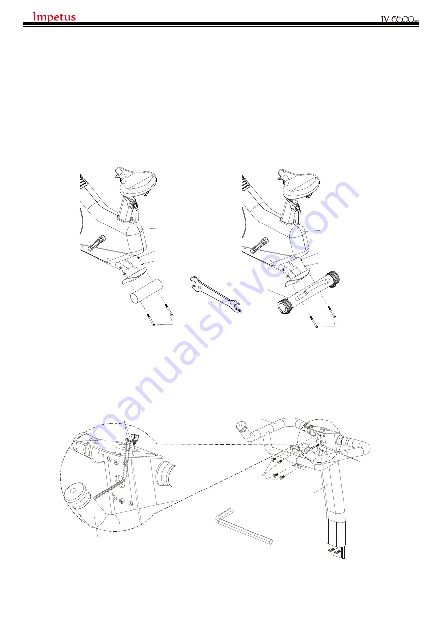
STEP 1
1. Remove pre-installed parts, two
NUTS (A7)
, two
WASHERS (A6)
, two
SCREWS (C4)
and a
PACKING TUBE,
from the
MAIN FRAME (A1)
.
2. Attach the
REAR STABILIZER (C1)
to the
MAIN FRAME (A1)
using two
NUTS (A7)
, two
WASHERS (A6)
and two
SCREWS (C4)
removed earlier.
STEP 2
1.Insert
WIRES (E6)
upward through the
UPRIGHT (B1)
as the picture shown.
2. Attach the
HANDLEBAR (E1)
to the
UPRIGHT (B1)
using four
SCREWS (E7)
.
6
ASSEMBLY INSTRUCTIONS :
A1
A7
A6
C4
A1
A7
A6
C4
C1
B1
E6
E1
E7
E1
E6
B1
5MM
Summary of Contents for IV 6500am
Page 1: ......
Page 5: ...5 PACKING LIST 6MM 5MM A1 B1 B2 C1 A30R A30L E7...
Page 11: ...11...
Page 12: ...12...
Page 13: ...13...


