background image

32

L

E

N

H

E

A

T

E

R


2

L

E

N

L

I

N

E

IMMERSUN

L

E

N

H

E

A

T

E

R


1

E

X


B

S

T

N

O

N

C

C

RELAY

Wiring: Underfloor Heating (opt. 1)

4

LOAD

ISOLATOR

SUPPLY

ISOLATOR

3.2KW max.

UFH MAT

L N  E

220-240VAC

SUPPLY

L  N  E

UFH

THERMOSTAT

SUPPLY

ISOLATOR

HEATING DEVICE

& THERMOSTAT

L N  E

L N  E

3.2KW max.

L  N  E

220-240VAC

SUPPLY

Summary of Contents for automatic power controller

Page 1: ...1 ENGLISH Installation User Guide V1 2...

Page 2: ...linking units immerSUN at a glance Electrical Connections Sensor Installation Setup Wiring Diagrams Wiring Single Heater Wiring Two Heater Wiring Three Heater Wiring Underfloor Heating opt 1 Wiring Un...

Page 3: ...ogeneration systems including PV Wind and Hydro systems Clear graphical backlit LCD display Indicates current import export power levels as well as diverted power to the heater Savings are accurately...

Page 4: ...ection of the arrow between the Grid and House symbols Date Time The current date day of week and time Main Screen The main screen shows the status of the immerSUN the imported or exported power the d...

Page 5: ...been installed The savings can be displayed as a list or in a graph The savings are shown in kWh as well as financially in the chosen currency For the financial savings to be correct the user must ke...

Page 6: ...the amount of available export power this function is called Manual Boost and is activated from the main screen Once the boost starts the remaining boost period will be displayed this will start at 1...

Page 7: ...wish to change then press You can now edit the boost times use the and buttons to change the start time end time days of the week and heater number for the boost press the button to move to next sect...

Page 8: ...NGS Today 2 5kWh 0 36 Week 16kWh 2 30 Month 74kWh 10 15 Year 315kWh 45 09 Total 315kWh 45 09 SAVINGS Today 2 5kWh 0 36 Week 16kWh 2 30 Month 74kWh 10 15 Year 315kWh 45 09 Total 315kWh 45 09 BOOST TIME...

Page 9: ...screen gives an overview of the immerSUN configuration It is useful to check the current settings SET TARIFF Current 000 145 New 000 145 From 01 01 14 Press then use to make changes SET TARIFF Curren...

Page 10: ...o the load P W M Output voltage percentage Heatsink Temperature of the internal heatsink Protects Count of over current protections since switch on Sig Qual Signal quality of immerLINK wireless connec...

Page 11: ...11 Advanced options...

Page 12: ...ST p13 MAIN MENU Advanced Settings MAIN MENU Advanced Settings IMMERLINK IMMERLINK FACTORY RESET Reset Config Reset Savings Reset Immerlink Execute Press to cancel FACTORY RESET Reset Config Reset Sav...

Page 13: ...sequentially in the priority order Heater Thermostat The EX BST input will act as a thermostat for the selected heater s The heater output will only be active when there is a signal at the EX BST inp...

Page 14: ...ticked the relay will also operate during timed or manual boost When Boosting The relay will operate whenever the selected heater s are being boosted either with manual boost or timed boost Boiler Bo...

Page 15: ...will immediately deactivate and will remain so for the set OFF Period This function operates independent to the heater outputs When the Priority is set to HIGH the relay will activate when the surplu...

Page 16: ...r 1 and Heater 2 outputs However it is possible to simply switch ON OFF other types of devices by using the Threshold option of the Multifunction Relay Cylinder Destratification The effective capacity...

Page 17: ...y of LCD screen Adequate ventilation keep vents clear and provide airflow around the unit Mimi mum clearance top and bottom is 50mm although more is recommend for ease of access to case screws Cable a...

Page 18: ...TER WIND TURBINE PV ARRAY DISTRIBUTION BOARD ELECTRICITY GRID IMMERSUN OTHER LOADS SENSOR CLAMP WATER HEATER or other heater GENERATION METER TERMINAL BLOCK ROOM HEATER optional Wireless Sensor option...

Page 19: ...ol all slaves via the wireless immerLINK Each slave must be powered from the same phase as the master Each slave must have its own load The sensor does NOT connect to the slave devices immerLINK is a...

Page 20: ...20 immerSUN at a glance 6 4 6 3 1 2 4 5 External overview 1 LCD display 2 Control buttons 3 Cover removable 4 Cover screws 5 Bottom panel removable 6 Bottom panel screws...

Page 21: ...erminal plug 2 LINE terminal plug mains supply input 3 HEATER 1 terminal plug 4 HEATER 2 terminal plug 5 RELAY terminal plug Multifunction Relay 6 Cooling fan 7 EX BST terminal plug External Boost inp...

Page 22: ...choose the most appropriate wiring scheme for the installation Important Earth MUST be connected Ensure wires are secure in screw terminals Check plugs are fully inserted Secure cables to the cable an...

Page 23: ...ted via Henley Block If the PV system is connected via a terminal then the clamp should be installed on the grid side of the block i e between the meter and terminal block More than one consumer unit...

Page 24: ...Setup...

Page 25: ...25 Wiring diagrams...

Page 26: ...26 L E N HEATER 2 L E N LINE IMMERSUN L E N HEATER 1 EX BST NO NC C RELAY HEATER THERMOSTAT LOAD ISOLATOR 3 2KW max SUPPLY ISOLATOR Wiring Single Heater 1 L N E 220 240VAC SUPPLY...

Page 27: ...load isolator can be eliminated if the immerSUN and the supply isolation switch are located near the heater Important Maximum load 3 2KW Minimum load 150W Recommended cable size 2 5mm Must be a simple...

Page 28: ...L E N HEATER 2 L E N LINE IMMERSUN L E N HEATER 1 EX BST NO NC C RELAY Wiring Two Heater 2 HEATER THERMOSTAT 3 2KW max SUPPLY ISOLATOR L N E 220 240VAC SUPPLY LOAD ISOLATORS 3 2KW max HEATER THERMOST...

Page 29: ...more heat The heating priority can be set in the Main Menu Set Priority Also the period of time between heater checks can be set in the Advanced Settings Menu Priority Check When both heaters are HOT...

Page 30: ...L E N HEATER 2 L E N LINE IMMERSUN L E N HEATER 1 3 2KW max SUPPLY ISOLATOR L N E 220 240VAC SUPPLY EX BST NO NC C RELAY LOAD ISOLATORS 3 2KW max HEATER THERMOSTAT HEATER THERMOSTAT LOAD ISOLATOR 3 2...

Page 31: ...rity heater the immerSUN will switch to the higher priority heater periodically to check if it can take more heat The heating priority can be set in the Main Menu Set Priority Also the period of time...

Page 32: ...HEATER 1 EX BST NO NC C RELAY Wiring Underfloor Heating opt 1 4 LOAD ISOLATOR SUPPLY ISOLATOR 3 2KW max UFH MAT L N E 220 240VAC SUPPLY L N E UFH THERMOSTAT SUPPLY ISOLATOR HEATING DEVICE THERMOSTAT L...

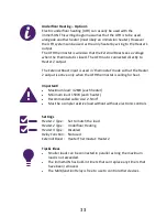
Page 33: ...in thermostat mode so that the Heater 2 output is active only when the UFH thermostat is calling for heat Important Maximum load 3 2KW each heater Minimum load 150W each heater Recommended cable size...

Page 34: ...E N LINE IMMERSUN L E N HEATER 1 EX BST NO NC C RELAY L N E L 5 LOAD ISOLATOR SUPPLY ISOLATOR 3 2KW max UFH MAT UFH THERMOSTAT HEATING DEVICE THERMOSTAT 3 2KW max L N E 220 240VAC SUPPLY Wiring Under...

Page 35: ...t The External Boost input is used in thermostat mode so that the Heater 2 output is active only when the UFH thermostat is calling for heat Important Maximum load 3 2KW each heater Minimum load 150W...

Page 36: ...36 Wiring Dual Tariff Single Meter...

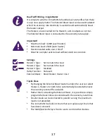
Page 37: ...ithout electronic controls Settings Heater 1 Type Set to match the load Heater 2 Type Set to match the load Heater 3 Type Disabled Relay Function Not used External Boost Boost Heater Heater 1 2 Tips I...

Page 38: ...ER 1 EX BST NO NC C RELAY Wiring Dual Tariff Two Meters 7 3 2KW max L N E 220 240VAC 24hr SUPPLY HEATER THERMOSTAT LOAD ISOLATOR 3 2KW max HEATER THERMOSTAT A1 A2 1 3 5 7 2 4 6 8 220 240VAC SUPPLY off...

Page 39: ...With this configuration only Heater 2 will be able to be billed at the economy rate Important Maximum load 3 2KW each heater Minimum load 150W each heater Recommended cable size 2 5mm Must be a simpl...

Page 40: ...this could damage the unit THE UNIT SHOULD NEVER BE BACK FED Check The wiring must be incorrect check wiring 3 HEATER NOT DETECTED During setup the unit did not detect any current begin draw by Heater...

Page 41: ...e ventilation and the vents are not blocked OUTPUT OVERLOAD The output current is too high the heater connected is too large Check The heater KW rating it should be less than 3 2kW and more than 150W...

Page 42: ...98 Power Factor 1 0 Power Control Method PWM Control Resolution 0 33 Response Time 1 second Measurement Accuracy 1 Dimensions 235 x 152 x 72mm IP Classification IP20 Compliance EN 60335 1 2012 Househo...

Page 43: ...d physical sensory or mental capabilities or lack of experience and knowledge unless they have been given supervision or instruction Children being supervised not to play with the appliance Product Di...

Page 44: ...44 4eco Ltd Church View Business Park Binbrook Lincolnshire LN8 6BY England 44 0 1472 398838...

Reviews: