12
C13
1-10
C13
1-11
1
2
4
5
6
7
3
INS
TALLER
US
ER
MAINTEN
AN
CE TECHNI
CI
AN
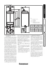
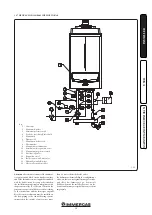
The kit includes:
N° 1 - Adaptor Ø 80/125 (1)
N° 1 - Gasket (2)
N° 1 - Concentric bend Ø 80/125 a 87° (4)
1 - Int./exhaust concentric terminal
80/125 Ø (5)
N° 1 - Internal ring (6)
N° 1 - External ring (7)
1.14 CONCENTRIC HORIZONTAL KIT
INSTALLATION.
Type C configuration, sealed chamber and
fan assisted.
Installation of this terminal must comply with
the provisions set forth by all of the legislation
and regulations in force which may allow, in
certain cases, wall flue exhaust for low-NOx
condensing boilers.
The position of the terminal (in terms of dis-
tances from openings, overlooking buildings,
decking, etc.) must be set up in compliance
with technical regulations in force as well as the
references of good technique (ex.: EN 15287) for
generators with a single maximum nominal heat
input of 35 kW (ex.: Victrix Pro 35 1 I installed
individually) and also for generators with a single
maximum nominal heat input of 35 kW.
This terminal is connected directly to the outside
of the building for air intake and flue exhaust. The
horizontal kit can be installed with the rear, right
side, left side or front outlet. For installation with
frontal outlet, one must use the fixing plate and
a concentric bend coupling in order to ensure
sufficient space to carry out the tests required
by law upon commissioning.
• External grid. The intake/exhaust terminal,
if properly installed, is pleasant to look at on
the outside of the building. Make sure that
the external silicone sealing plate is properly
inserted in the wall.
Horizontal intake-exhaust kit Ø 80/125
Kit
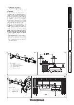
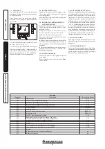
assembly (Fig. 1-10): install the 80/125 Ø adapter
(1) on the central hole of the boiler fully home.
Slide the gasket (2) along the adapter (1) up to
the relevant groove, fix it to the lid using the
previously disassembled sheet steel plate (3).
Engage the bend (4) with the male side (smooth)
until it is fully home on the adapter (1). Fit the Ø
80/125 (5) concentric terminal pipe with the male
end (smooth) to the female end of the bend (4)
(with lip seals) up to the stop; making sure that
the internal (6) and external wall sealing plates
(7) have been fitted, this will ensure sealing and
joining of the elements making up the kit.
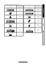
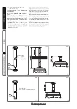
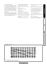
• Maximum length (MAX L) (Fig. 1-11). The kit
with this configuration can be extended up to a
max. measurement of 8.0 m with Victrix Pro 35
1 I and 14.5 m for Victrix Pro 55 1 I
, including
the grid-covered terminal and the concentric
bend on the boiler outlet.
Summary of Contents for VICTRIX PRO 35 1 I
Page 1: ...VICTRIX PRO 35 55 1 I IE Instruction and warning book 1 038715ENG...
Page 2: ......
Page 42: ......
Page 43: ......


