


20
1-26A
1-26B
A
B
C
D
E
F
G
H
1-25
INS
TALLER
US
ER
MAINTEN
AN
CE TECHNI
CI
AN
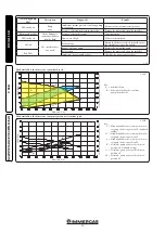
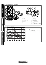
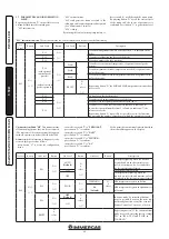
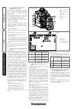
Key:
C = Head available to the system with circula-
tor pump selector in position C4 (standard
setting)
D = Head available to the system with circula-
tor pump selector in position C3
E = Head available to the system with circula-
tor pump selector in position P2
F = Circulator pump power with selector in
position C4 (standard setting)
G = Circulator pump power with selector in
position C3
H = Circulator pump power with selector in
position P2
Head available to the direct zone system fixed speed.
Head available to the direct zone system proportional or constant speed.
Key:
A = Available head
B = Power absorbed by the circulator
pump (dotted area)
Ci
rcu
la
to
r p
um
p a
bs
or
be
d p
ow
er (
W
)
Ci
rcu
la
to
r p
um
p a
bs
or
be
d p
ow
er (
W
)
Flow rate (l/h)
Flow rate (l/h)
H
ea
d (kP
a)
H
ea
d (kP
a)
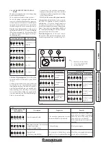
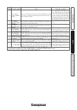
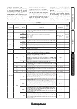
Circulating pump
LED
Description
Diagnostics
Remedy
LED steady on
Pump
noisy
Insufficient system pressure, circulating pump
in cavitation
Restore correct thermal circuit pressure
Presence of foreign matter in the impeller
Remove the motor and clean the impeller
Flashing white LED
Noises during cir-
culation of the heat
transfer fluid
Presence of air in the system
Vent the system
LED steady on
Flow rate too high
Reduce rotation speed
LED off
The circulator does
not work
Power outage
Ensure the boiler is correctly powered, ensure
the circulator is correctly powered
Faulty circulating pump
Replace the circulating pump
Red LED
Rotor seized
Remove the motor and clean the impeller
Insufficient power supply voltage
Check boiler power supply voltage
MAX
MIN