background image

(

A

)

(

B

)

1-7

9

INS

TALLER

US

ER

MAINTEN

AN

CE TECHNI

CI

AN

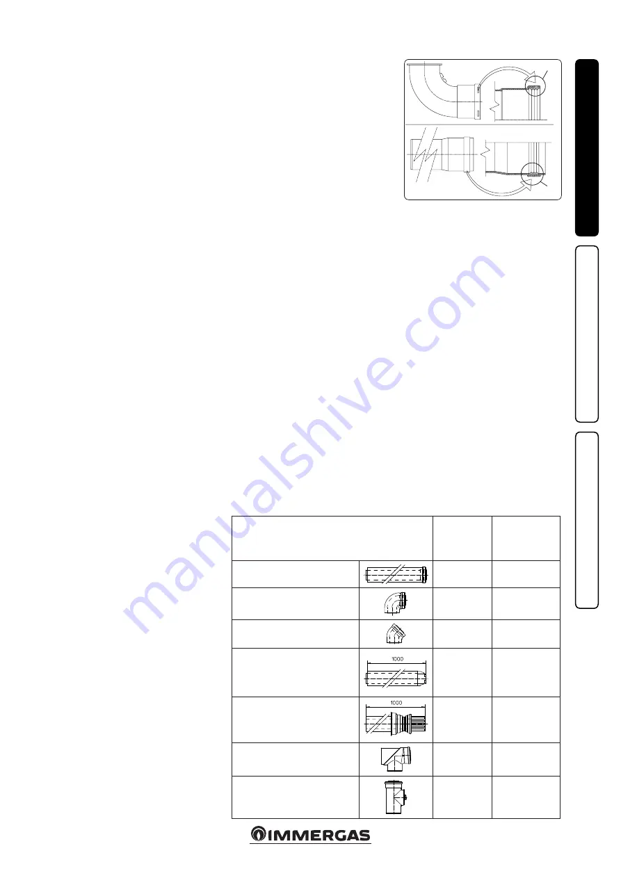
1.9  TABLES OF RESISTANCE FACTORS 

AND EQUIVALENT LENGTHS.

TYPE OF DUCT

Resistance

Factor

(R)

Equivalent length 

in m of concentric 

pipe Ø 80/125

Concentric pipe Ø 80/125 m 1

2.1

1

Concentric bend 90° Ø 80/125

3.0

1.4

Concentric bend 45° Ø 80/125

2.1

1

Terminal complete with concentric 

horizontal intake-exhaust Ø 80/125

2.8

1.3

Terminal complete with concentric 

vertical intake-exhaust Ø 80/125

3.6

1.7

Concentric bend 90° Ø 80/125 with 

inspection

3.4

1.6

Stub pipe with inspection Ø 80/125

3.4

1.6

1.8   IMMERGAS FLUE SYSTEMS.

Immergas supplies various solutions separately 

from the boilers regarding the installation of 

air intake terminals and flue exhaust, which are 

fundamental for boiler operation.

Attention: the boiler must be installed ex-

clusively with an original Immergas “Green 

Range” inspectionable air intake system and 

fumes extraction system made of plastic, with 

the exception of the C6 configuration, as re-

quired by the regulations in force.
The plastic pipes cannot be installed outdoors, 

for tracts longer than 40 cm, without suitable 

protection from UV rays and other atmos-

pheric agents.
This system can be identified by an identifica-

tion mark and special distinctive marking 

bearing the note: “only for condensing boilers”.

•  Resistance factors and equivalent lengths. Each 

flue component has a 

Resistance Factor

 based 

on experimental tests and specified in the table 

below. The Resistance Factor for individual 

components is independent from the type of 

boiler on which it is installed and has a dimen-

sionless size. It is however, conditioned by the 

temperature of the fluids that pass through the 

pipe and therefore, varies according to applica-

tions for air intake or flue exhaust. Each single 

component has a resistance corresponding to 

a certain length in metres of pipe of the same 

diameter; the so-called 

equivalent length

can be obtained from the ratio between the 

relative Resistance Factors. 

All boilers have an 

experimentally obtainable maximum Resistance 

Factor equal to 100.

 The maximum Resistance 

Factor allowed corresponds to the resistance 

encountered with the maximum allowed pipe 

length for each type of Terminal Kit. This 

information allows calculations to be made to 

verify the possibility of setting up various flue 

configurations.

• 

Positioning the gaskets (black) for “green 

range” flue systems.

 Position the gasket cor-

rectly (for bends and extensions) (Fig. 1-7):

  - gasket (A) with notches, to use for bends;
  -  gasket (B) without notches, to use for exten-

sions;

 N.B.:

 if component lubrication (already car-

ried out by the manufacturer) is not sufficient, 

remove the residual lubricant using a dry cloth, 

then to ease fitting coat the parts with talc, sup-

plied in the kit.

• Coupling extension pipes and concentric 

elbows. To install push-fitting extensions with 

other elements of the flue, proceed as follows: 

Install the concentric pipe or elbow with the 

male side (smooth) on the female side (with lip 

seal) to the end stop on the previously installed 

element in order to ensure sealing efficiency of 

the coupling.


Attention:

 if the exhaust terminal and/or 

concentric extension pipe needs shortening, 

consider that the internal duct must always 

protrude by 5 mm with respect to the external 

duct.

• 

N.B.:

 for safety purposes, do not obstruct the 

boiler intake/exhaust terminal, even temporar-

ily.

• 

N.B.:

 when installing horizontal pipes, a mini-

mum inclination of 3% must be maintained and 

a section clip with pin must be installed every 

3 metres.

Summary of Contents for Hercules Condensing 26 3 ErP

Page 1: ...HERCULES CONDENSING 26 3 32 3 ERP Instruction and recommendation booklet IE 1 037970ENG ...

Page 2: ......

Page 3: ...he regulations in force and principles of good workmanship In compliance with legislation in force the systems must be designed by qualified professionals within the dimensional limits established by the Law Installation and maintenance must be performed in compliance with the regulations in force according to the manufacturer s instructions and by professionally qualified staff intending staff wi...

Page 4: ...ing and maintenance 21 2 2 General warnings 21 2 3 Control panel 21 2 4 Description of functioning states 22 2 5 Using the boiler 23 2 6 Troubleshooting 24 2 7 Boiler shutdown 25 2 8 Restore central heating system pressure 25 2 9 System draining 25 2 10Cylinder draining 25 2 11Antifreeze protection 25 2 12Case cleaning 26 2 13Decommissioning 26 2 14Parameters and information menu 26 3 Boiler commi...

Page 5: ...of the reach of children If the appliance is installed in side or between cabinets ensure sufficient space for normal servicing therefore it is advisable to leave clearance of at least 30 cm on the right of the boiler in order to open the lateral hatch and a space of 3 cm between the remaining sides of the boiler and the sides of the cabinet Leave adequate space above the boiler for possible water...

Page 6: ...erature system return G 1 optional MB2 Zone 2 low temperature system flow G 1 optional RB1 Zone 1 low temperature system return G 1 optional MB1 Zone 1 low temperature system flow G 1 optional RA1 Zone 1 high temperature system return G 3 4 MA1 Zone 1 high temperature system flow G 3 4 G Gas supply G 1 2 AC DHW output G 3 4 AF DHW inlet G 3 4 RC Recirculation G 3 4 optional RP Return to solar pane...

Page 7: ...on of drinking water we recommend installing the IMMERGAS anti backflow kit to be used upstream of the cold water inlet connection of the boiler It is also recommended that the heat transfer fluid e g water glycol entered in the primary circuit of the boiler heating circuit complies with the local regulations in force Attention to preserve the duration and the ef ficiency features of the appliance...

Page 8: ...n sheet to position the external probe The probe can be connected directly to the boiler electrical system and allows the max system flow temperature to be automatically decreased when the external temperature increases in order to adjust the heat supplied to the system according to the change in external tempera ture The external probe always operates when connected regardless of the presence or ...

Page 9: ... pass through the pipe and therefore varies according to applica tions for air intake or flue exhaust Each single component has a resistance corresponding to a certain length in metres of pipe of the same diameter the so called equivalent length can be obtained from the ratio between the relative Resistance Factors All boilers have an experimentally obtainable maximum Resistance Factor equal to 10...

Page 10: ...Intake and Exhaust 16 3 m 2 5 Intake m 18 7 Exhaust m 4 9 m 7 7 Exhaust m 13 6 Concentric vertical intake exhaust terminal Ø 60 100 Intake and Exhaust 9 m 1 4 Intake m 10 3 Exhaust m 2 7 m 4 3 Exhaust m 7 5 Pipe Ø 80 m 1 Intake 0 87 m 0 1 Intake m 1 0 Exhaust m 0 4 m 0 4 m 0 5 Exhaust 1 2 m 0 2 Exhaust m 1 0 Complete intake terminal Ø 80 m 1 Intake 3 m 0 5 Intake m 3 4 Exhaust m 0 9 m 1 4 Intake t...

Page 11: ...rooms the flue gas exhaust must be connected to its own individual flue or ducted directly into the external atmosphere Type B open chamber boilers must not be installed in places where commercial artisan or industrial activities take place which use products that may develop volatile vapours or substances e g acid vapours glues paints solvents combustibles etc as well as dusts e g dust deriving f...

Page 12: ...ntal m in cluding the terminal with grid and excluding the concentric bend leaving the boiler This configurationcorrespondstoaresistancefactor of 100 In this case the special extensions must be requested Immergas also provides a Ø 60 100 simplified terminal which in combination with its exten sion kits allows you to reach a maximum exten sion of 11 9 metres Horizontal intake exhaust kit Ø 80 125 K...

Page 13: ...nto the flange 2 up to the stop making sure that the wall sealing plate has been fitted 3 this will ensure sealing and joining of the elements making up the kit Note when the boiler is installed in areas where very rigid temperatures can be reached a special anti freeze kit is available that can be installed as an alternative to the standard kit Extensions for vertical kit Ø 60 100 Fig 1 14 The ki...

Page 14: ...ce it with the flange 3 positioning the gasket 2 already present in the boiler and tighten using the supplied self threading screws Fit the male side smooth to the bends 5 in the female side of the flanges 3 and 4 Fit the intake terminal 6 with the male side smooth in the female side of the bend 5 up to the end stop ensuring that the internal and external wall sealing plates are fitted Fit the exh...

Page 15: ... the external pipe must be fitted on the adaptor until it stops 1 N B to encourage the removal of possible condensate forming in the exhaust pipe tilt the pipes towards the boiler with a minimum slope of 1 5 Mount the cover A complete with adaptor 1 and caps 6 on the wall and assemble the flue system to the ducting system N B version Ø 125 only before assembly check the gaskets are in the right po...

Page 16: ...gth of the Ø 80 rigid ducting vertical section is equal to 30 m This length is obtained considering the complete Ø 80 exhaust terminal 1m of Ø 80 pipe in exhaust two 90 Ø 80 bends on the boiler outlet 1 16 CONFIGURATION TYPE B OPEN CHAMBER AND FAN ASSISTED FOR INDOORS The appliance can be installed inside buildings in B23 or B53 mode in this case all technical rules and national and local regulati...

Page 17: ...e operations turn on the circu lating pump at intervals using the main switch on the control panel Vent the circulation pump by loosening the front cap and keeping the motor running and assuring that the liquid that escapes cannot cause injury damage to persons objects Tighten the cap after the operation Attention to carry out the filling procedure correctly activate the automatic vent function se...

Page 18: ...er and set the desired curve Attention there is a burns hazard due to high fluid temperature and pressure Burns hazard from coming in contact 1 23 CIRCULATION PUMP Boilers in the Hercules Condensing ErP series are supplied with 2 types of circulating pumps Set operation modes according to one s installa tion requirements Boiler circulator pump The circulating pump is not equipped with speed select...

Page 19: ...ided into high tem perature zones radiators and low temperature zones floor plants in order to interlock them with separate adjustments and to keep water flow rate high for each zone Immergas supplies the low temperature kit on request Solar panels kit on demand If solar panels are to be used for the production of domestic hot water Immergas supplies the solar panels kit on demand Low temperature ...

Page 20: ...4 Zone 1 one way valve 5 Zone 1 pump 6 Safety thermostat Low temperature optional 7 Flow probe Low temperature optional 8 Zone 2 pump optional 9 Mixing valve optional 10 Flue probe 11 Condensation module 12 Burner 13 Ignition electrode 14 Detection electrode 15 Venturi 16 Gas nozzle 17 Fan 18 Cold water inlet cock 19 8 bar safety valve 20 Air intake pipe 21 3 bar safety valve 22 D H W expansion ve...

Page 21: ... rain sunlight etc the appliance power cable must not be re placed by the user in the event of damage to the cable switch off the appliance and contact exclusively quali fied staff for replacement if the appliance is not to be used for a certain period disconnect the main power switch N B the temperatures indicated by the display have a tolerance of 3 C due to environmental conditions that cannot ...

Page 22: ...a request for domestic hot water or central heating in order to evacuate residual flue gas F5 Postcirculation in progress Pump in function after a request for domestic hot water or central heating in order to cool the primary circuit P33 With Remote Control Optional or room thermostat TA Optional in block the boiler functions all the same in central heating mode Can be activated through menu M3 It...

Page 23: ...the event of connection to the Super CAR remote control the boiler automatically detects the device and the symbol appears on the display From this moment it is possible to make adjustments indifferently from the Super CAR remote control or the boiler Except for the central heating tempera ture that is shown on the display but managed by the Super CAR remote control Attention if the boiler is put ...

Page 24: ...boiler pressure gauge 1 that the system pressure is between 1 1 2 bar and restore the correct pressure if necessary 12 Storage tank probe anomaly The board detects an anomaly on the storage tank probe The boiler cannot produce domestic hot water domestic water heating is carried out by the solar system and Pdc 1 15 Configuration error If the board detects an anomaly or incongruity on the electric ...

Page 25: ...ist of errors in the M1 menu only If normal conditions are restored the boiler restarts without having to be reset 1 47 Burner power limitation Should flue high temperature be detected the boiler reduces power sup plied so as not to damage it 1 1 If the shutdown or fault persists contact an authorised firm e g Authorised Technical After Sales Service 2 7 BOILER SHUTDOWN Switch the boiler off by pr...

Page 26: ...l Button 3rd Level Button Description M1 D C P11 D C View the management software version of the P C B installed in the boiler P12 View the total functioning hours of the boiler P13 View the number of burner ignitions P14 with optional external probe present without external probe optional D C P14 A View the current external temperature if optional external probe present P14 B View the minimum ext...

Page 27: ...e restored A1 proceed as follows press button D to access the configuration menu turn selector switch 3 to PERSONAL press button D to confirm turn selector switch 3 to DATI press button D to confirm turn selector switch 3 to LINGUA press button D to confirm turn selector switch 3 to A1 press button D to confirm At this point the international items indicated in the menu tables appear on the displa...

Page 28: ... do not commission the system 3 1 PLUMBING DIAGRAM Key 1 Stainless steel coil for storage tank 2 System draining valve 3 Storage tank unit return one way valve 4 Polyphosphate dispenser optional 5 System filling valve 6 3 bar safety valve 7 Manifold draining valve 8 Condensate drain trap 9 Gas valve 10 Gas valve outlet pressure point P3 11 Air intake pipe 12 Fan 13 Gas nozzle 14 Detection electrod...

Page 29: ...ite Y Yellow 1 230 Vac 50 Hz power supply 2 Super CAR Optional 3 Status signal 4 IMG BUS connection 5 System supervisor connection 6 Storage tank configuration jumper 7 External probe connection active 8 S34 setting 9 Supervisor connection active 10 Domestic hot water 11 Central heating Remote controls the boiler is designed for use with the Comando Amico Remoto remote control V2 CARV2 or alternat...

Page 30: ...caused by dirt or combustion products deposited inside Check by means of the condensate drain cap that there are no residues of material blocking the flow of condensate Heat exchanger clogged This may be caused by the drain trap being blocked Check by means of the condensate drain cap that there are no residues of material blocking the flow of condensate Noise due to air in the system Check openin...

Page 31: ... P65 Below find the default settings present on the boiler Hercules Condensing 26 3 ErP P62 G20 5060 rpm LPG 4400 rpm P63 G20 1240 rpm LPG 1140 rpm P64 G20 4700 rpm LPG 4100 rpm P65 G20 1240 rpm LPG 1140 rpm Hercules Condensing 32 3 ErP P62 G20 4700 rpm LPG 4200 rpm P63 G20 1260 rpm LPG 1160 rpm P64 G20 4700 rpm LPG 4200 rpm P65 G20 1260 rpm LPG 1160 rpm 3 6 ADJUSTMENT OF THE AIR GAS RATIO Calibra...

Page 32: ...xternal probe present it defines the minimum flow temperature corresponding to operation with maximum external temperature see graph Fig 1 6 it can be set between 20 C and 50 C N B to continue one must confirm the parameter press D or exit adjustment P66 by pressing C 20 C P66 B Without the external probe optional it defines the maximum flow temperature With the external probe present it defines t...

Page 33: ...he storage tank falls by 3 C with respect to the temperature set Solar function deactivated P71 1 P71 2 5 C Boiler ignition for heating the domestic hot water occurs when the water contained in the storage tank falls by 5 C with respect to the temperature set Solar function active if the input domestic hot water has a sufficient temperature the boiler does not switch on P72 AUTO OFF 09 L M 12 L M ...

Page 34: ...s the pump at least once every 24 hours for the duration of 30 seconds in order to reduce the risk of the pump becoming blocked due to prolonged inactivity 3 11 THREE WAY ANTI BLOCK FUNCTION Both in domestic hot water and in domestic hot water central heating phase the boiler is equipped with a function that starts the three way motorised group 24 hours after it was last in operation running it fo...

Page 35: ...hamber lid otherwise it must be replaced Visually check that the water safety valves drain is not blocked Check after discharging the system pressure and bringing it to zero read on boiler pressure gauge that the expansion vessel charge is at 1 0 bar Check that the domestic hot water expansion vessel charge is at a pressure between 3 and 3 5 bar Check that the system static pressure with system co...

Page 36: ...emove the screw 16 in the top corner of the door 15 Release the door 15 from the bracket just released from the screw 16 bending it out wards and sliding it off of the lower pin 17 Casing disassembly Fig 3 7 undo the front screws 7 push the front slightly upwards 6 in order to free it from the lower fixing slots and pull it towards yourself detail A remove the front half cover 8 loosening the inte...

Page 37: ...3 7 6 7 7 14 14 14 14 14 13 9 8 11 11 10 12 9 Part B Part A 37 INSTALLER USER MAINTENANCE TECHNICIAN Part B Part A ...

Page 38: ...1 0 91 1 10 11 2 0 90 1 51 15 4 10 0 8600 1 12 1 19 12 2 0 83 0 93 9 5 0 82 1 30 13 2 9 0 7740 1 01 1 02 10 4 0 75 0 78 8 0 0 74 1 10 11 2 8 0 6880 0 90 0 85 8 6 0 67 0 64 6 5 0 66 0 91 9 3 7 0 6020 0 79 0 69 7 0 0 59 0 52 5 3 0 58 0 74 7 5 6 0 5160 0 68 0 54 5 5 0 50 0 41 4 2 0 50 0 58 5 9 5 0 4300 0 57 0 40 4 1 0 42 0 32 3 3 0 42 0 44 4 5 4 7 4042 0 53 0 36 3 7 0 40 0 30 3 1 0 39 0 40 4 1 METHAN...

Page 39: ...Flue temperature at nominal output C 78 86 79 Flue temperature at minimum output C 73 82 75 Hercules Condensing 32 3 ErP Gas nozzle diameter mm WITHOUT 6 00 6 00 Flue flow rate at nominal heat output kg h 52 47 53 Flue flow rate at min heat output kg h 12 11 12 CO2 at Q Nom Min 9 40 8 90 12 30 11 90 10 50 10 30 CO with 0 O2 at Nom Min Q Nom Min ppm 206 9 640 8 190 8 NOX at 0 of O2 at Q Nom Min mg ...

Page 40: ... central heating temperature C 25 85 25 85 Min adjustable central heating temperature C 25 50 25 50 System expansion vessel total volume l 10 8 10 8 Heating expansion vessel pre charge bar 1 0 1 0 Total volume domestic hot water expansion vessel l 4 1 4 1 Domestic hot water expansion vessel pre charge bar 3 5 3 5 Appliance water content l 6 0 6 7 Head available with 1000 l h flow rate kPa m H2 O 2...

Page 41: ...Sr N Serial Number CHK Check Cod PIN PIN code Type Type of installation ref CEN TR 1749 Qnw min Minimum DHW heat input Qn min CH minimum heat input Qnw max DHW maximum heat input Qn max CH maximum heat input Pn min Minimum heat output Pn max Maximum heat output PMS Maximum system pressure PMW Maximum domestic hot water pressure D Specific flow rate TM Maximum operating temperature NOx Class NOx Cl...

Page 42: ...ns 60 C on return and 80 C on flow Low temperature mode for condensation Boilers means 30 C for low temperature boilers 37 C and for other appliances 50 C of return tempera ture Model s Hercules Condensing 32 3 ErP Condensing Boilers SI Low temperature boiler NO Boiler type B1 NO Co generation appliance for central heating NO Fitted with supplementary heating system NO Mixed heating appliance SI E...

Page 43: ...c hot water function AFC 18 GJ Seasonal room heating yield ηs 90 Domestic hot water production yield ηwh 78 Parameter value Yearly energy consumption for the heating function QHE 61 2 GJ Yearly electricity consumption for the domestic hot water function AEC 42 kWh Yearly fuel consumption for the domestic hot water function AFC 18 GJ Seasonal room heating yield ηs 92 Domestic hot water production y...

Page 44: ...lementary heat pump From fiche of heat pump Solar contribution and Supplementary heat pump Select smaller value Boiler and supplementary heat pump installed with low temperature heat emitters at 35 C From fiche of heat pump The energy efficiency of the package of products provided far in this fiche may not correspond to its actual energy efficiency once installed in a building as the efficiency is...

Page 45: ...fiche of heat pump The energy efficiency of the package of products provided far in this fiche may not correspond to its actual energy efficiency once installed in a building as the efficiency is influenced by further factors such as heal loss in the distribution system and the dimensioning of the products in rela tion to building size and characteristics Seasonal space heating energy efficiency o...

Page 46: ...r contribution From fiche of solar device 1 I 2 1 1 x I 10 x II III I Auxiliary electricity 3 G F E D C B A A A A 27 27 27 28 27 27 27 28 30 30 30 32 33 34 35 36 36 37 38 40 39 50 55 60 65 75 80 85 100 115 123 131 130 150 160 170 163 188 200 213 M L XL XXL 3 2 3 2 The energy efficiency of the package of products provided far in this fiche may not correspond to its actual energy efficiency once ins...

Page 47: ...ting energy efficiency under colder and warmer climate conditions Colder 0 2 x Warmer 0 4 x Declared load profile Solar contribution From fiche of solar device 1 _____ 2 1 1 x _____ 10 x _____ ____ ______ Auxiliary electricity 3 G F E D C B A A A A 27 27 27 28 27 27 27 28 30 30 30 32 33 34 35 36 36 37 38 40 39 50 55 60 65 75 80 85 100 115 123 131 130 150 160 170 163 188 200 213 M L XL XXL 3 2 3 2 ...

Page 48: ...48 ...

Page 49: ...49 ...

Page 50: ...50 ...

Page 51: ...51 ...

Page 52: ...immergas com Immergas S p A 42041 Brescello RE Italy Tel 0522 689011 Fax 0522 680617 Certified company ISO 9001 This instruction booklet is made of ecological paper Cod 1 037970ENG rev ST 001520 002 03 17 Inglese per IRLANDA IE ...

Reviews: