background image

5

1-1

INS

TALLER

US

ER

MAINTEN

AN

CE TECHNI

CI

AN

1

 INSTALLATION  

BOILER

1.1 INSTALLATION 

RECOMMENDATIONS.

The Eolo Star 24 5 E boiler has been designed for 

wall mounted installation only, for heating and 

production of domestic hot water for domestic 

use and similar purposes.

The place of installation of the appliance and 

relative Immergas accessories must have suitable 

features (technical and structural), such as to al-

low for (always in safe, efficient and comfortable 

conditions):

- installation (according to the provisions of 

technical legislation and technical regulations);

-  maintenance operations (including scheduled, 

periodic, routine and special maintenance);

- removal (to outdoors in the place for loading 

and transporting the appliances and com-

ponents) as well as the eventual replacement 

of those with appliances and/or equivalent 

components.

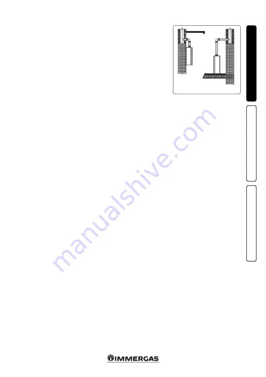
The wall surface must be smooth, without any 

protrusions or recesses enabling access to the 

rear part. They are not designed to be installed 

on plinths or floors (Fig. 1-1).

By varying the type of installation the classifica-

tion of the boiler also varies, precisely:

- Type B

22

 boiler 

if installed using the relevant 

terminal for air intake directly from the room 

in which the boiler has been installed.

- Type C boiler

 if installed using concentric 

pipes or other types of pipes envisioned for 

the sealed chamber boiler for intake of air and 

expulsion of fumes.

Only professionally enabled companies are 

authorised to install Immergas gas appliances.

Installation must be carried out according to 

regulation standards, current legislation and in 

compliance with local technical regulations and 

the required technical procedures.

Important:

 Immergas declines all liability for 

damages caused by boilers removed from other 

systems or for any non-conformities of such 

equipment.

Before installing the appliance, ensure that it 

is delivered in perfect condition; if in doubt, 

contact the supplier immediately. Packing ma-

terials (staples, nails, plastic bags, polystyrene 

foam, etc.) constitute a hazard and must be kept 

out of the reach of children. If the appliance is 

installed inside or between cabinets, ensure suf-

ficient space for normal servicing; it is therefore 

recommended to leave at least 45 cm between 

the upper part of the boiler and the ceiling and 

a gap of 3 cm between the boiler casing and the 

vertical sides of the cabinet. Keep all flammable 

objects away from the appliance (paper, rags, 

plastic, polystyrene, etc.).

Do not place household appliances underneath 

the boiler as they could be damaged if the safety 

valve intervenes (if not conveyed away by a 

draining funnel), or if there are leaks from the 

hydraulic connections; otherwise, the manufac-

turer cannot be held responsible for any damage 

caused to the household appliances.

For the aforementioned reasons, we recommend 

not placing furnishings, furniture, etc. under 

the boiler.

In the event of malfunctions, faults or incorrect 

operation, turn the appliance off and contact an 

authorised company (e.g. the Technical Assistan-

ce centre, which has specifically trained staff and 

original spare parts). Do not attempt to modify 

or repair the appliance alone.

Failure to comply with the above implies personal 

responsibility and invalidates the warranty.

• Installation Standards:
  - this boiler can be installed outdoors in a 

partially protected area. A partially protected 

area is one in which the boiler is not exposed 

to the direct action of the weather (rain, snow, 

hail, etc..).

NOTE: 

this type of installation is only possible 

when permitted by the laws in force in the 

appliance's country of destination.

  - Installation of gas appliances, flue exhaust 

pipes and combustion air intake pipes is 

forbidden in places with a fire risk (for 

example: garages, closed parking stalls), and 

in potentially dangerous places.

  - Installation is prohibited on the vertical 

projection of the cooking surface.

  - Installation is forbidden in places/rooms 

that constitute public areas of apartment 

buildings, internal stairways or other escape 

routes (e.g. floor landings, entrance halls, 

etc.).

  -  Installation is also forbidden in places/rooms 

that constitute public areas of apartment bu-

ildings such as cellars, entrance halls, attics, 

lofts, etc., unless otherwise provided for by 

local regulations in force.

Attention

: wall mounting of the boiler must 

guarantee stable and efficient support for the 

generator.

The plugs (standard supply) are to be used only 

in conjunction with the fixing template to fix the 

boiler to the wall;

 they only ensure adequate sup-

port if inserted correctly (according to technical 

standards) in walls made of solid or semi-hollow 

brick or block. In the case of walls made from 

hollow brick or block, partitions with limited 

static properties, or in any case walls other than 

those indicated, a static test must be carried out 

to ensure adequate mount.

N.B.: the hex head screws supplied in the blister 

pack are to be used exclusively to fix the relative 

mounting bracket to the wall.

These boilers are used to heat water to below 

boiling temperature in atmospheric pressure.

They must be connected to a central heating 

system and domestic hot water circuit suited to 

their performance and capacity.

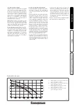
YES

NO

Summary of Contents for EOLO STAR 24 5E

Page 1: ...EOLO STAR 24 5E IE Instructions and warning book 1 040471ENG ...

Page 2: ......

Page 3: ...rs As for the other issues related to boiler installation e g safety in the work site environment protection injury prevention it is necessary to comply with the provisions specified in the regulations in force and principles of good practice In compliance with the legislation in force the systems must be designed by qualified professionals within the dimensional limits established by the Law Inst...

Page 4: ...22 Circulation pump 17 1 23 Kits available on request 17 1 24 Boiler components 18 2 Instructions for use and maintenance 19 2 1 Cleaning and maintenance 19 2 2 General warnings 19 2 3 Control panel 19 2 4 Fault and anomaly signals 20 2 5 Information Menu 22 2 6 Boiler shutdown 22 2 7 Restore central heating system pressure 22 2 8 Draining the system 22 2 9 Antifreeze protection 22 2 10 Case clean...

Page 5: ...hold appliances underneath the boiler as they could be damaged if the safety valve intervenes if not conveyed away by a draining funnel or if there are leaks from the hydraulic connections otherwise the manufac turer cannot be held responsible for any damage caused to the household appliances For the aforementioned reasons we recommend not placing furnishings furniture etc under the boiler In the ...

Page 6: ...sary with respect to the minimum temperature at which the system must be kept An aqueous solution must be made with potential pollution class of water 2 EN 1717 2002 or local stan dards in force Warning the excessive use of glycol could jeop ardise the proper functioning of the appliance The materials used for the central heating circuit of Immergas boilers withstand ethylene and propylene glycol ...

Page 7: ...ty before making the boiler connections carefully clean the heating system pipes radiators etc with special pickling or de scaling products to remove any deposits that could compromise correct boiler operation A treatment of the heating and water system wa ter is required in compliance with the technical standards in force in order to protect the system and the appliance from deposits e g scale sl...

Page 8: ...ssembly instructions contained in the accessory kit On Offdigitalchrono thermostat Thechrono thermostat allows set two room temperature value one for day comfort temperature and one for night reduced temperature set a weekly programme with four daily switch on and switch off times selecting the required function mode from the various possible alternatives manual mode with adjustable temperature au...

Page 9: ...phragms are supplied together with the boiler Attention only for installations with divided terminals 80 80 it is necessary to remove the plug located under the sealed chamber as shown in the Fig 1 8 Diaphragm Duct length in metres Ø 60 100 horizontal Ø 38 From 0 to 1 Ø 42 5 Exceeding 1 up to 3 Diaphragm Duct length in metres Ø 60 100 vertical Ø 38 From 0 to 3 2 Ø 42 5 Exceeding 3 2 up to 4 7 Diap...

Page 10: ...6 Exhaust m 2 0 Terminal complete with intake exhaust vertical concentric Ø 80 125 Intake and Exhaust 33 m 2 0 m 5 5 Intake m 14 3 Exhaust m 11 0 Intake exhaust terminal vertical concentric Ø 80 125 Intake and Exhaust 26 5 m 1 6 m 4 4 Intake m 11 5 Exhaust m 8 8 Terminal complete with intake exhaust horizontal concentric Ø 80 125 Intake and Exhaust 39 m 2 3 m 6 5 Intake m 16 9 Exhaust m 13 Intake ...

Page 11: ...he male end smooth of the exhaust terminal into the female end of the bend 90 Ø 80 making sure that the relevant wall sealing plate is already fitted this will ensure hold and joining of the elements making up the kit Max length of exhaust duct The flue pipe vertical or horizontal can be extended to a max length of 12 linear metres using insulated pipes Fig 1 26 To prevent problems of flue gas con...

Page 12: ... concentric terminal pipe Ø 60 100 3 with the male end smooth into the female end with lip seals of the bend 2 up to the stop making sure that the internal and external wall sealing plate have been fitted this will ensure sealing and joining of the kit elements Extensions for Ø 60 100 horizontal kit Fig 1 13 The kit with this configuration can be extended up to a max horizontal length of 3 m inclu...

Page 13: ... the intake exhaust pipe 6 Fit the Ø 80 125 concentric terminal pipewith themaleend 6 smooth tothefemale end of the adapter 3 with lip gasket up to the end stop making sure that the wall sealing plate 4 has been fitted this will ensure sealing and joining of the elements making up the kit Extensions for vertical kit Ø 60 100 Fig 1 17 The kit with this configuration can be exten ded to a max straig...

Page 14: ...ngth without bends usable for Ø 80 intake and exhaust pipes is 41 metres of which 40 intake and 1 exhaust This total length corresponds to a resistance factor of 100 The total usable length obtained by summing the Ø 80 intake and exhaust pipe lengths can reach as a maximum the values provided in the following table If mixed accessories or components are used the maximum extension can be calculated...

Page 15: ...air entering if very cold may cause the outside of the pipe to fall below the dew point of the environmental air The figures Fig 1 25 1 26 illustrate different applications of insulated pipes Insulated pipes are formed of a Ø 80 internal concentric pipe and a Ø 125 external pipe with static air space It is not technically possible to start with both Ø 80 elbows insulated as clearances will not all...

Page 16: ...ustion products must be in compliance with applicable standards Chimneys and roof installed exhaust terminals must com ply with the outlet height and with the distance from technical volumes set forth by the technical standards in force Positioningthewallflueexhaustterminals The wall flue exhaust terminals must be installed on external perimeter walls of the building be positioned according to the...

Page 17: ...ckwise it is excluded 1 23 KITS AVAILABLE ON REQUEST Connection unit kit on request The kit in cludes pipes fittings and cocks including gas cock to carry out all connections to the boiler system System cut off valve kits with or without in spectionable filter on request The boiler is designed for installation of system interception cocks to be placed on flow and return pipes of the connection ass...

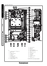
Page 18: ...ing valve 9 Positive signal pressure point 10 Negative signal pressure point 11 Flue pressure switch 12 Safety thermostat 13 Flue hood 14 Flow probe 15 Rapid heat exchanger 16 Ignition and detection electrodes 17 System expansion vessel 18 Burner 19 System pressure switch 20 Air vent valve 21 Boiler pump 22 Manifold 23 System draining valve 24 By pass 25 3 bar safety valve PLEASE NOTE connection g...

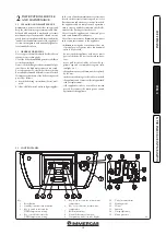
Page 19: ... to the high temperatures it can reach For safety purposes check that the air intake flue exhaust terminals if fitted are not blocked If temporary shutdown of the boiler is required proceed as follows a drain the heating system if anti freeze is not used b shut off all electrical water and gas supplies In the case of work or maintenance to structures located in the vicinity of ducting or devices f...

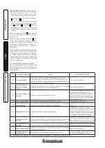
Page 20: ... excessive overheating internally the boiler goes into overheating block Press the Reset button 1 03 Flue safety thermostat anomaly Failure to recognise the flue pressure switch The boiler will automatically restart after 30 minutes without having to be reset After three interventions in less than two hours the boiler has to be manually rear med Restore the normal conditions and press the button R...

Page 21: ... Low power supply voltage This occurs when the power supply voltage is lower than the allowed limits for the correct boiler operation If normal conditions are restored the boiler restarts without having to be reset 1 38 Loss of flame signal This occurs when the boiler is ignited correctly and the burner flame switches off unexpectedly a new attempt at ignition is performed and if normal conditions...

Page 22: ...ater from an air vent valve of a radiator until reaching pressure of 1 bar or ask for assistance from professionally qualified personnel In the event of frequent pressure drops contact qualified staff for assistance to eliminate the possible system leakage 2 8 DRAINING THE SYSTEM To drain the boiler use the special draining valve Fig 2 2 Before draining ensure that the filling cock is closed 2 9 A...

Page 23: ...ream from the boiler check that the intake and or exhaust terminals are not blocked check activation of the no air safety pressure switch ensure activation of all adjustment devices seal the gas flow rate regulation devices if settings are modified 3 1 HYDRAULIC DIAGRAM ensure production of domestic hot water ensure sealing efficiency of water circuits check ventilation and or aeration of the inst...

Page 24: ...ease central heating temperature T1 Ignition transformer T2 Boiler P C B transformer X40 Room thermostat jumper Y1 Gas valve 1 User interface 2 230 Vac 50 Hz supply voltage Colour code key BK Black BL Blue BR Brown G Green GY Grey OR Orange P Purple PK Pink R Red W White W BK White Black Y Yellow Y G Yellow Green Comando Amico RemotoV2 the boiler is set up for the application of the Comando Amico ...

Page 25: ...complete calibration of the gas valve adjust the boiler nominal heat output adjust the boiler nominal heat output in domestic hot water phase adjust theboilernominalheatoutputinheating phase para 3 7 parameter P5 adjust eventually the maximum heating power para 3 7 parameter P6 after completing conversion apply the sticker present in the conversion kit near the data plate Using an indelible marker...

Page 26: ...ts up in heating mode if you wish to adjust the D H W open a hot water tap after the burner goes on Adjustparameterb02 observingthemaximum pressure values stated in the tables Para 3 15 depending on the type of gas Press the button 5 to increase the thermal power and button 6 to decrease it After the adjustment press and hold the reset button 1 to save the parameter Confirmation that the parameter...

Page 27: ...08 NOTE the selection of the Minimum heating output and Maximum heating output parameters in presence of a heating request allows boiler ignition and power supply of the modulator with current equal to the value of the respective set value 00 70 Set according to factory inspection P06 Maximum CH output 00 99 99 100 99 P07 Central heating ignitions timer The boiler has electronic timing which preve...

Page 28: ...LOCK FUNCTION In the summer functioning mode the boiler has a function that starts the pump at least once every 24 hours for 30 seconds in order to reduce the risk of the pump becoming blocked due to prolonged inactivity In the winter functioning mode the boiler has a function that makes the pump start at least once every 3 hours for 30 seconds 3 10 DOMESTIC HOT WATER CIRCUIT ANTI EXTRUDER FUNCTIO...

Page 29: ...ce the casing can be completely removed as follows Fig 3 4 Remove the plugs from the cover 1 by pulling them to you as shown by the arrows Undo the 2 front screws 2 and the 2 lower screws 3 which fasten the casing 4 Pull the casing 4 towards yourself and up at the same time to detach it from the upper hooks ...

Page 30: ...20 BUTANE G30 PROPANE G31 HEAT THERMAL HEAT THERMAL CH D H W GAS FLOW RATE BURNER PRESS NOZZLE BURNER GAS FLOW RATE BURNER PRESS NOZZLE BURNER GAS FLOW RATE BURNER PRESS NOZZLE BURNER kW kcal h m3 h mbar mm H2 O kg h mbar mm H2 O kg h mbar mm H2 O 23 8 20468 2 70 11 40 116 3 2 01 28 20 287 6 1 98 36 30 370 2 23 0 19780 2 61 10 65 108 6 1 94 26 30 268 2 1 91 33 97 346 4 21 9 18806 2 48 9 65 98 4 1 ...

Page 31: ... with burner On Off 0 6 0 46 Heat loss at flue with burner On Off 6 0 0 03 Central heating circuit max operating pressure bar 3 Maximum central heating temperature C 90 Adjustable central heating temperature C 35 80 System expansion vessel total volume l 4 2 Heating expansion vessel pre charge bar 1 0 Appliance water content l 0 7 Head available with 1000 l h flow rate kPa m H2 O 30 4 3 1 Domestic...

Page 32: ...G Md Model Code Md Model code Sr N Serial Number CHK Check Code PIN PIN code Type Type of installation ref CEN TR 1749 Qnw min Minimum DHW heat input Qn min CH minimum heat input Qnw max DHW maximum heat input Qn max CH maximum heat input Pn min Minimum heat output Pn max Maximum heat output PMS Maximum system pressure PMW Maximum domestic hot water pressure D Specific flow rate TM Maximum operati...

Page 33: ......

Page 34: ......

Page 35: ......

Page 36: ...alia immergas com Immergas Europe S r o 05951 Poprad Matejovce SK Tel 421 524314311 Fax 421 524314316 Certified company ISO 9001 This instruction booklet is made of ecological paper Cod 1 040471ENG rev ST 002959 001 11 17 ...

Reviews: